Only one pin assignment differs
First, I investigated the wiring of later-model ABS systems based on the service manual supplement (September 1999).
Late-model ABS systems have a very simple configuration, as the control unit is built into the modulator assembly.
The only difference in the pin assignment between the NK8 modulator for the AP1 (S2000) and the modulator for the NSX is the warning light signal (WALP).
In other words, by swapping terminal 11 of a commercially available NSX conversion harness with terminal 7 of the AP1 system, the AP1 modulator can be used.
TCS Output Support Unknown
The NSX modulator converts the signals from the rotation sensors on each wheel into pulses and outputs them to the TCS unit.
I was unable to verify this because I had completely removed the TCS, but since the AP1 does not have traction control, I am unsure whether the output for the TCS unit works.
The coupler for the AP1 that I received along with the modulator had the TCS signal line closed with a rubber plug, and there was no wiring at all.
Since the TCS control is rather crude and offers few benefits, it may be a good idea to remove it when replacing the car.
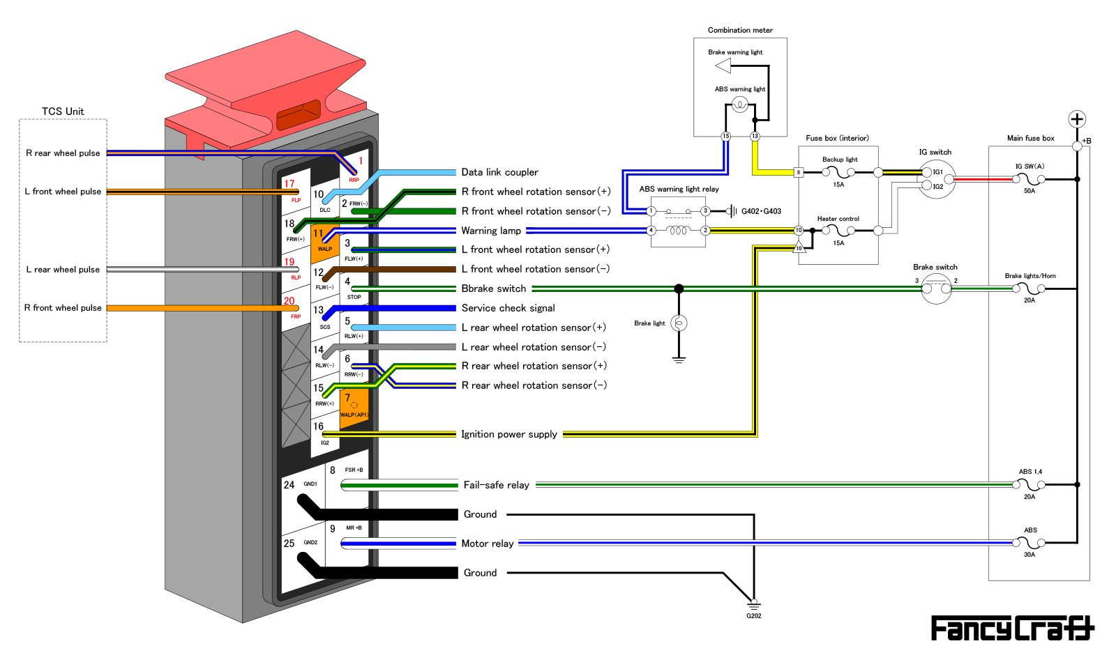
NSX late model ABS modulator wiring diagram
Circuits Absent in Later ABS
In later ABS models, the control unit is built into the modulator, but in earlier ALB models, a separate control unit is located inside the vehicle, making the wiring more complex.
Early ALB models incorporate circuits that later ABS models do not have, such as a charging warning light and brake warning light, and also have signal lines for driving the solenoid and fail-safe relay, as well as signal lines for the pressure switch, so the number of wires is significantly greater than later ABS models.
ALB Warning Light System
Aside from unnecessary wiring, the other major difference is the operating principle of the ALB warning light.
With early ALBs, the ALB unit connects the negative side of the ALB warning light to ground when a malfunction occurs, which causes it to light up.
With later ABSs, the signal output from the modulator is on when normal, and turns off when a malfunction occurs, causing the warning light to light up via an NC contact relay.
If the warning light signal wire from the later modulator is connected as is, the warning light will function in the opposite way, so an additional NC contact relay will be required.
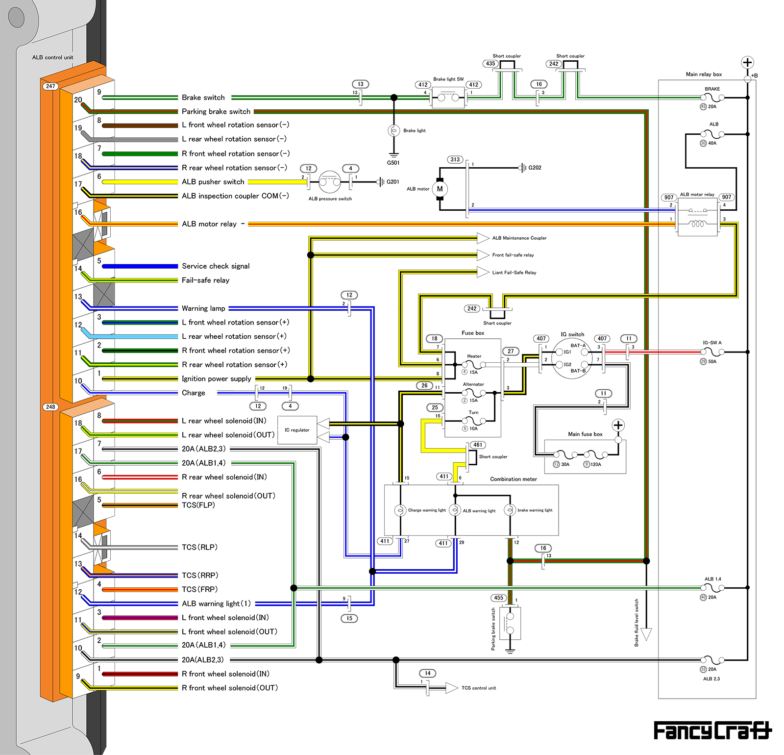
NSX early ALB wiring diagram
Warning Light Relay & Motor Power
Wiring for the wheel rotation sensors and other components can be connected as is, but an NC contact relay must be added to the warning light illumination circuit.
The power supply for the additional warning light illumination relay is connected by branching off the ignition power supply, just like the early ALB.
In the early ALB, the motor drive relay is housed in the main relay box, but the later ABS modulator has a built-in motor drive relay, so power is supplied directly to the modulator.
Therefore, it is necessary to short-circuit the relay and supply power directly, or connect the relay's signal line to ground to keep it constantly powered.
*The wiring diagram shows the signal line grounded.
Fail-safe relay power supply
Furthermore, the later ABS modulator also has a built-in failsafe relay, so this power wire must also be connected directly. The power supply to the failsafe relay of the later ABS is via a 20A fuse, so the wiring that can be used with the earlier ALB is the power wire of terminal 17 (terminal 2) of the 478 coupler. The 478 coupler is only composed of wiring for solenoid drive and TCS unit output. Since the later ABS does not use solenoid drive related wiring, if the TCS is canceled, only the power wire for the failsafe relay is required.
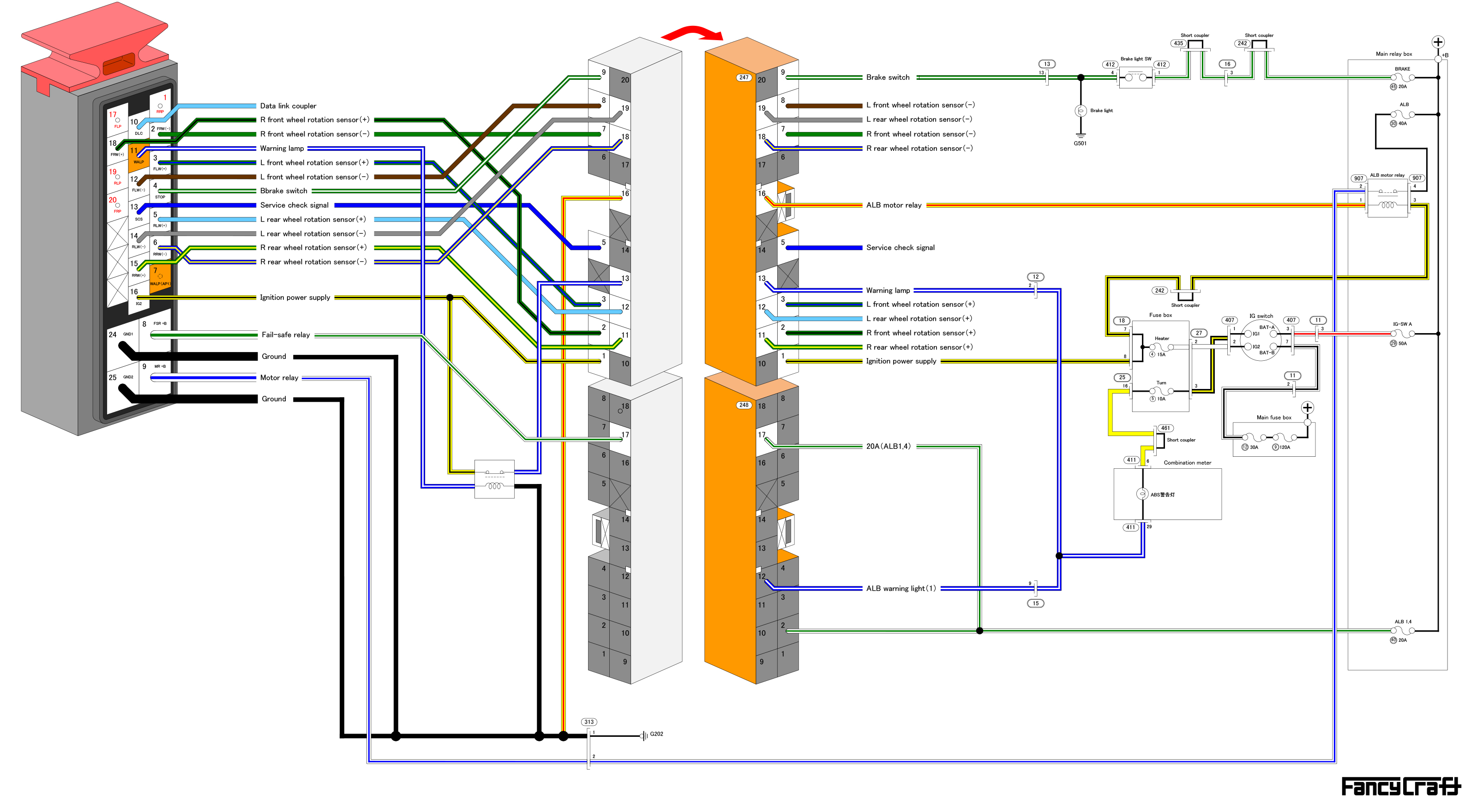
NSX late model ABS replacement wiring diagram
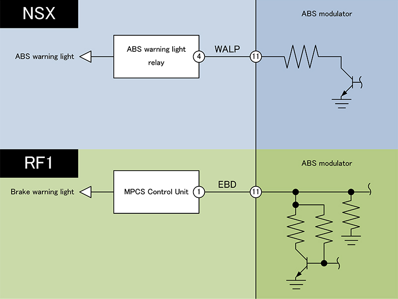
Difference between NSX and Step WGN (RF1) terminal 11
For Step Wagon (RF1)
The wiring for the RF1 is basically the same as the AP1, with the exception that the warning light relay signal is on terminal 7.
However, with the RF1, the vehicle speed pulse for the right front wheel (terminal 20) is connected to the power sliding door control unit and used for fail-safe functions such as stopping the door while driving, and terminal 11 is used for a different purpose.
- Terminal 11 of RF1 is input to the MPCS control unit and is treated as an active LOW (LOW = normal) logic flag signal to control the brake warning light according to the state of the brake system.
It may seem like this terminal could be used as a signal to turn on the warning light, but since the NSX's ABS warning light circuit is relay-driven (current loop type fail-safe) and has a different design concept, terminal 11 of RF1 should not be used as a warning light drive signal.
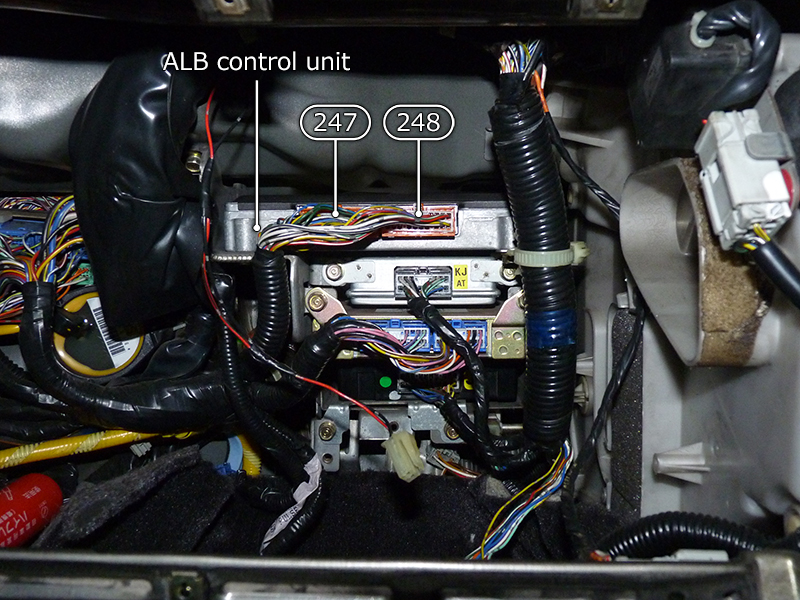
ALB control unit location
- When you remove the glove box on the passenger side, you can see several units behind it. The top one of these units is the ALB control unit, and the two couplers plugged into it are coupler 247 and coupler 248 on the wiring diagram . In later ABS models, the modulator and control unit are integrated, so the ALB control unit can be removed when replacing the ABS.
Removed ALB control unit
- The removed ALB control unit.
The unit cannot be removed alone, so the bracket that secures all the units must be removed before the ALB control unit can be separated.
The actual weight of the ALB control unit was 0.934 kg.
Ref.: Weight Reduction Project - Body Partsopen_in_new

Removal of unused wiring for later ABS
- There is no service hole to allow new wiring to be routed through for the wiring connected to the later modulator, so it is necessary to route it through the grommet in the bulkhead that pulls the main harness into the interior. This grommet is located deep inside the fuse box, making it difficult to route the new wiring.
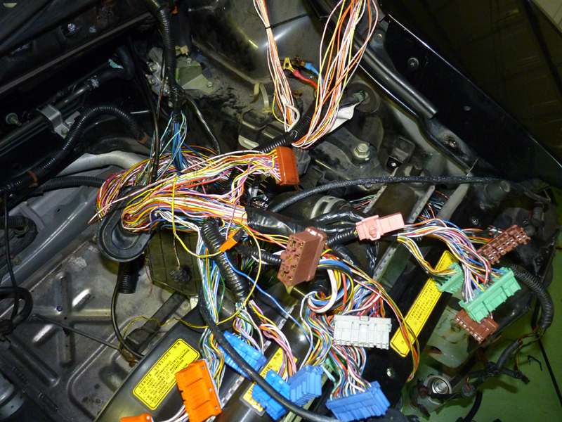
While peeling off the harness tape to route the new wiring, I decided to take this opportunity to remove unnecessary wiring as well, and so I started removing the wiring that was not being used for the later ABS.
While working, I had many regrets and thought, "I should have just given up," but I am the type of person who cannot tolerate large amounts of unnecessary wiring remaining, so I persevered.
The work was very difficult, but after removing the unnecessary wiring related to the ALB as well as the fog lamp wiring and measuring the weight, it came out at 0.714 kg, which was lighter than I expected.
Ref.: Weight Reduction Project - Electrical Equipmentopen_in_new
- After completing the wiring, start the engine and first confirm that the ALB check lamp on the instrument panel comes on and then turns off properly.
If the check lamp turns off, this indicates that the built-in control unit is operating normally. The only way
to check the operation of the modulator itself is to actually operate it, so I will deliberately create a situation where the ABS will activate.
Since triggering ABS on a normal paved road can be dangerous, I will test it in a location with a low friction coefficient.
Braking hard on dirt or gravel roads will activate the ABS quite easily, even at speeds as low as 10 km/h.
When the ABS activates, the "buzzing" sound of the actuator can be clearly heard from inside the vehicle.
The test is completed by driving around town for a while to confirm that the ABS not only activates when the wheels are locked, but also does not activate during normal driving.
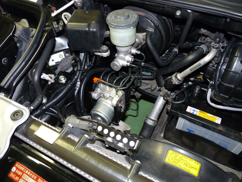
ABS modulator replacement and wiring completed