
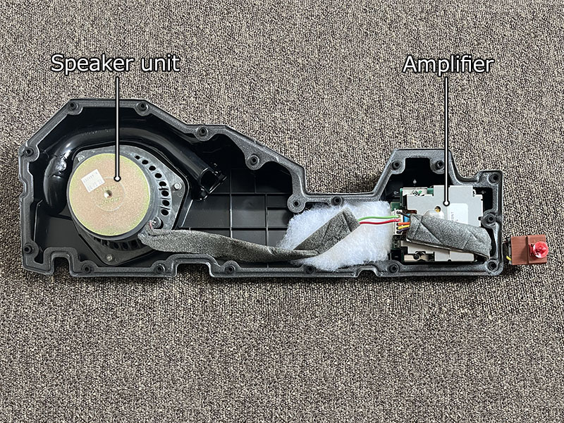
NSX genuine BOSE door speaker internals
Factory BOSE Active System
- In most factory car audio systems, the amplifier is built into the head unit, making them passive speaker systems. In contrast, the NSX factory BOSE system is an active setup, with an amplifier built into each speaker.
- Only signal lines run from the head unit to the amplifiers in the left and right door speakers and the subwoofer (footwell subwoofer) (*). Power for each amplifier is supplied separately from the speaker relay in the relay box.
* Only the rear speakers do not have separate amplifiers and are driven via the amplifier built into the subwoofer.
- Most passive speaker systems use 4‑ohm speakers. However, the units built into the NSX factory BOSE speakers measured approximately 0.9 ohms, which is considerably lower.
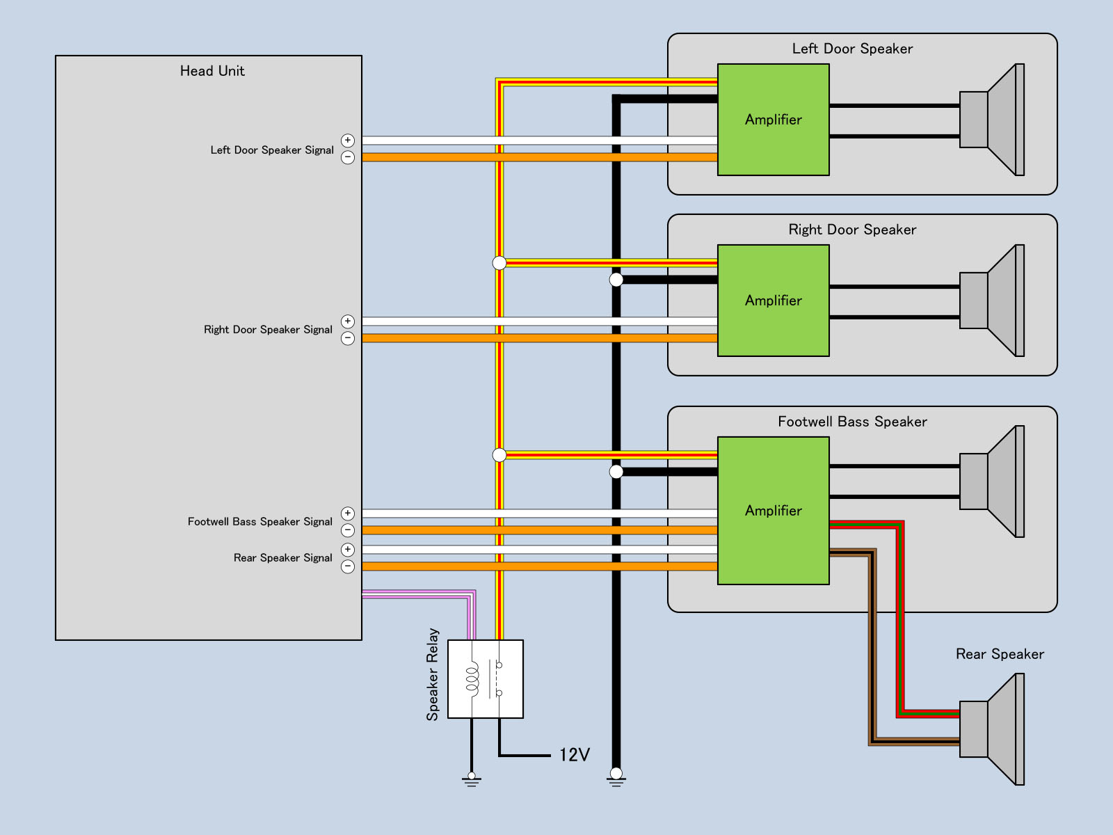
NSX genuine BOSE system connection diagram

NSX Genuine BOSE Speaker Impedance Measurement
Checking the Genuine BOSE Unit
- The upper and lower brackets used to mount the unit to the vehicle are integrated into the chassis, making it a dedicated unit. The size appears to be close to a standard 2DIN unit.
- The genuine BOSE head unit used in the NSX is known to be manufactured by ALPINE. The label on the back of the head unit shows the manufacturer name (ALPINE) and the wiring diagram for the connector.
- The labels attached to the side and rear of the unit appear to contain manufacturing control codes.
- Although the front panel of the genuine BOSE head unit has a trapezoidal shape, the measured size of the main unit is W179×H95 mm.
The standard 2DIN size is W180×H100, so although the vertical dimension is slightly different, it can be considered almost the same size as a 2DIN unit.

NSX Genuine BOSE Head Unit

Head Unit Bottom Label ①

Head Unit Bottom Label ②

NSX Genuine BOSE Head Unit Dimensions
Aftermarket 2DIN Head Unit
Although it would have been possible to retain the original BOSE system, considering convenience and the risk of failure, I decided to replace it with a typical aftermarket head unit.
- The original BOSE head unit has special dimensions, so it is not possible to install an aftermarket head unit directly. To install it, I initially used the one-piece version of the " Bracket Kit for Single & Double DIN Stereos open_in_new " from Science of Speed. I used the old model with a one-piece structure (it has now been redesigned to a two-piece structure).
- The head unit I purchased at the time was carrozzeria FH-770DVDopen_in_new. I chose it because it has a touch panel and the illumination and display text can be changed to the same orange color as the original. The Science of Speed bracket is secured with only two screws on the bottom, but there was no wobble whatsoever.

Science of Speed 2DIN bracket

Head Unit with Science of Speed Bracket
KSP Engineering Stay Kit
- The bracket made by Science of Speed was difficult to use because it allowed stepless front-to-back adjustment of the head unit, so I eventually switched to the KSP Engineering KS-8507 Audio Mounting Bracketopen_in_new.
- In the photo, the upper bar is temporarily fastened, but this bar is designed to be fixed by removing the original screw grommet and clamping the dash-side stay in place. Because it is not an area that requires much force, when I tried to fix it with the original screws, the center of the hole on the bracket and the screw grommet did not line up, so I removed the screw grommet and installed it using the bar.
- The fuse capacity of the ACC power supply is low at 10A, which is a concern, probably because the head unit does not require a power supply for the amplifier. However, the connection to the vehicle side is a 16P coupler for Honda vehicles ( 16PNBC-572Hopen_in_new etc.) can be used.

KSP Engineering KS-8507 Audio Mounting Bracket

Temporarily attach the stay kit to the head unit
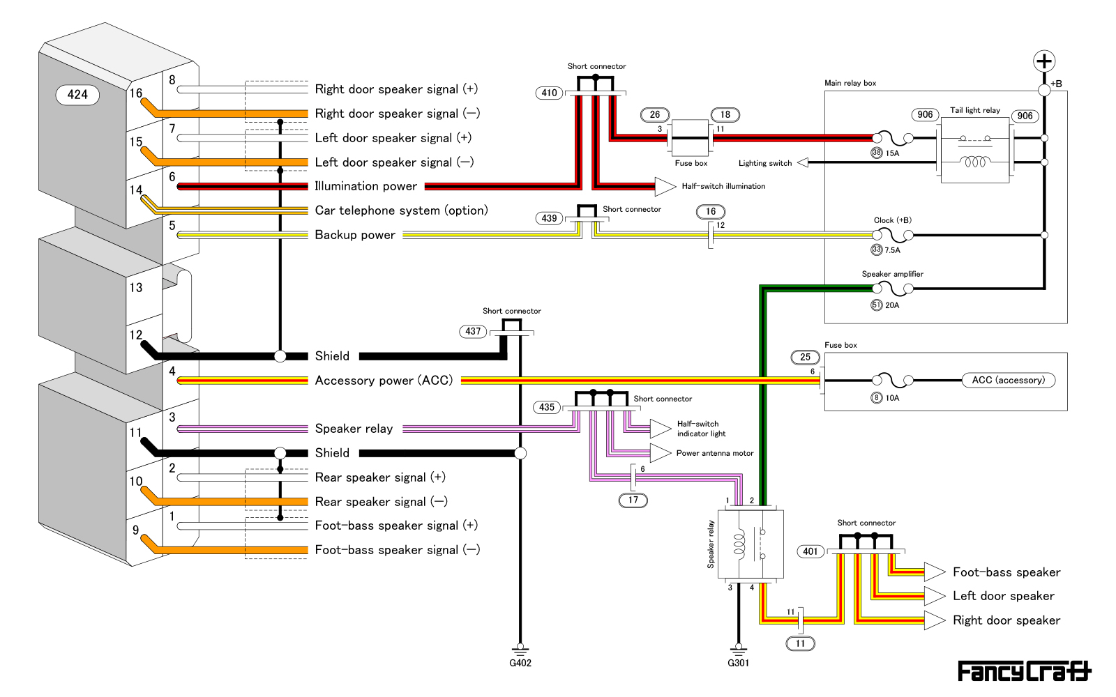
NSX genuine BOSE audio system wiring diagram

Square Holes in Door Panel for Baffle Mounting
- Around the hole where the protruding part on the back of the factory speaker fits, there are four square holes for screw grommets, as if they were prepared for attaching a baffle board. One of the four square holes is already in use to secure the factory speaker, so screw grommets are added to the remaining three to attach the baffle board.

Screw Grommets 90662-693-003 & 90665-SM4-000
- The screw grommets used to secure the speakers vary in color depending on the model; from 1991 to 1993 they were blue, and from 1994 onwards they were yellow. I was curious to see what the difference was, so I bought both and compared them, but I couldn't find any difference in shape. The early blue ones are more expensive, so I think it would be better to choose the yellow ones.
Loading...
| No | Part Number | Part Name | unit price | quantity | price | remarks |
|---|---|---|---|---|---|---|
| 90662-693-003 | Grommet, Screw, 4mm (Blue) | 1 | 1991-1993 | |||
| 90665-SM4-000 | Grommet, Screw, 4mm (Yellow) | 1 | Since 1994 |
All prices shown include tax.

Homemade wood baffle & aftermarket speakers

Homemade wooden baffle board dimensions
- I made the baffle board from scrap wood, using a router to cut the large center hole. The speakers I purchased were carrozzeria TS-J1700Aopen_in_new. Since it is a 2-way type, it comes with a separate crossover network in addition to the speaker unit itself.
- Dimensions of the temporary baffle board. I made the speaker mounting holes exactly diagonally, so they ended up being too close to the holes for fixing them to the door. If the holes are too close together, it could cause the baffle board to crack, so it might be better to rotate the speaker slightly to shift the hole positions. Also, the back of the baffle board needs to be partially chamfered to cushion the bulge of the door panel.
- Aftermarket speakers mounted using a baffle board. The back of the speaker unit is exposed to water dripping from the glass, so we recommend waterproofing it.

Aftermarket Speakers with DIY Wooden Baffle
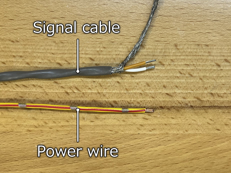
Genuine BOSE Signal & Power Cable Comparison
- The original Bose system has an amplifier mounted inside the enclosure, so it connects two signal wires and two power wires—a total of four. The signal wires are significantly thinner than typical cables for head unit direct-drive speakers. Therefore, I decided to use the power wires instead for speaker connection. Measurements were taken with a vernier caliper, so there may be some error. The signal wires are 20 pieces of 0.1mm diameter plated wire (finished outer diameter 1.5mm), and the power wires are 20 pieces of 0.2mm diameter copper wire (finished outer diameter 2mm). Calculating the cross-sectional area based on the measured dimensions yields approximately 0.16 sq mm for the signal wires and approximately 0.63 sq mm for the power wires. However, considering Japanese specifications, the signal wires are not 0.3 sq mm and the power wires are not 0.75 sq mm. Considering that typical speaker cables are 0.5 to 0.75 sq mm, the signal wires are a little thinner. Therefore, I decided to use the power wires, which I believe offer the advantage in terms of sound quality, as the speaker cables connecting to the head unit. (The power wires require modification because they connect to a relay.)
I tried installing aftermarket 17cm speakers on a homemade baffle board, but I felt that the sound was a bit muffled compared to the original system before the replacement, so I decided to try some sound deadening.
- I purchased two cheap vibration-damping sheets measuring 500mm x 1000mm for 1,150 yen, but they are quite heavy, which is a disadvantage in terms of driving performance.
- To avoid unnecessary weight gain, we accurately molded the door hole area where the vibration-damping sheet would be attached, and created a template with a 10mm margin for attachment.
- When I tested it with the damping sheet installed, the sound felt more muffled than before. To treat the door itself as an enclosure, many measures would be necessary, such as properly creating ducts and placing anti-reflection sponges on the back of the speakers, but since I don't have specialized knowledge about acoustics and I don't want to improve sound quality by increasing the weight, I removed the vibration-damping sheet and returned it to its original state.

Purchased deadening vibration-damping sheet

Stencils made from construction paper

After attaching the vibration-damping sheet
Since the deadening did not give good results, I decided to focus first on redesigning the baffle board to a more optimal shape. After creating the basic design using 3D CAD, I planned to refine it through repeated test production, but since the final goal was to replace the 4Ω speaker unit with the original enclosure, this plan was discontinued after just the design stage. The 3D CAD software used at this time was Autodesk 123D (*).
* Autodesk 123D has now been integrated into the company's "Fusion360" and is no longer available. Also, Fusion360 offers a limited-function version (Personal Autodesk Fusionopen_in_new) that allows access to basic functions for free, but only for non-commercial projects at home.) is being distributed.
Baffle board 3D CAD dataopen_in_new (f3d file 139KB)
* Since we do not actually manufacture this product, we cannot guarantee that it will fit.

Baffle board design in 123D (Fusion360)