Removing the steering column
The NSX has very narrow foot space, and the brake pedal cannot be replaced without removing the steering column, so we first remove the steering column.
- After removing the steering wheel, remove the interior panel under the meter panel (instrument driver lower panel), the metal panel inside it (instrument driver lower frame), and the interior panel under the feet (driver under cover). Once the interior panel is removed, you will be able to access the bolts and nuts that secure the connectors and steering column, so first remove all of the connectors.
- The universal joint can be seen by removing the plastic cover (steering joint cover) at the base of the steering column on the body side.
Remove the M8 bolt on the steering side of the universal joint so that the shaft can be removed from the joint.
The bolt fits into a groove cut perpendicular to the spline at the end of the shaft, so the shaft will not come out just by loosening the bolt.
Marking the position of the shaft and joint will make it easier to determine the angle when inserting it.
In this state, remove the two M8 flange nuts and two M8 bolts that secure the steering column and the steering column will separate.
×
![Popup Image]()
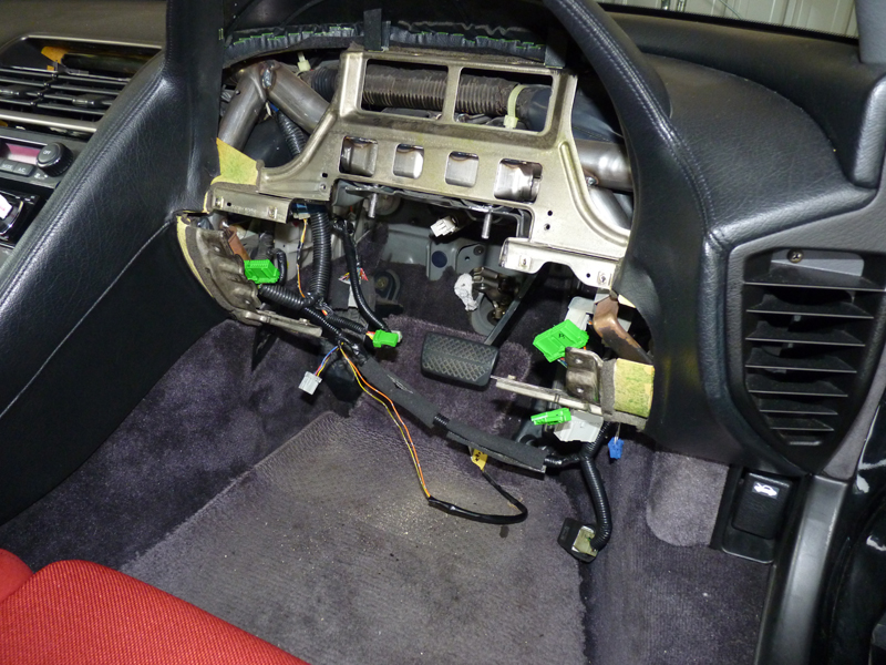
Obstructive parts removed
- The steering column has been removed, making it easier to access the pedals (the instrument panel has also been removed, but the steering column can be removed without removing it).
×
![Popup Image]()
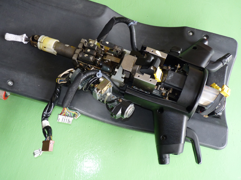
Removed steering column
- The removed steering column.
In the photo, the column cover is still attached, but it may be better to remove it beforehand to prevent scratches during removal and storage.
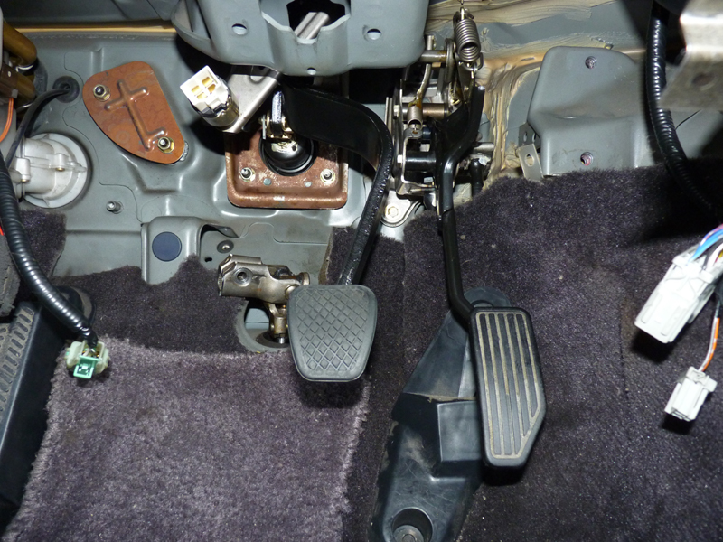
Brake pedal replacement
×
![Popup Image]()
After replacing the MT brake pedal
- At first, I thought I'd remove the pedal bracket and install the pedals, but even after removing the nuts and separating the pedal bracket, the bracket interfered with the body before it could be removed from the stud bolt on the master back, making it impossible to remove.
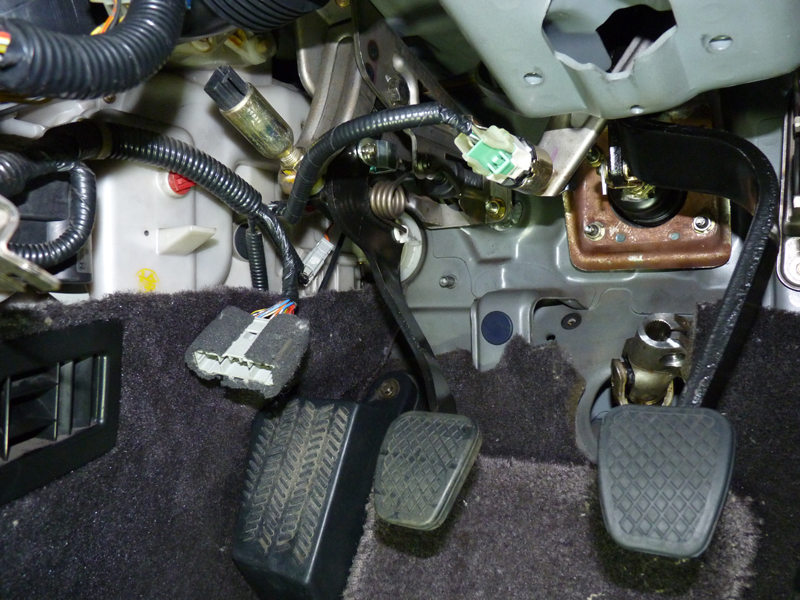
Even when I pushed the master back as hard as I could, the stud bolt didn't move down far enough to remove the pedal bracket.
It's possible I overlooked something, but I think the pedal bracket can't be removed without removing the master back.
Since I wanted to avoid removing the master back, I thought I'd just replace the pedals with the pedal bracket still attached to the body, but the space was too narrow and I couldn't access the pedal fixing bolts with the tools I had.
So, I separated the pedal bracket and managed to replace it by changing its orientation.
It was difficult, but still easier than removing the master back.
Clutch pedal installation
×
![Popup Image]()
After installing the clutch pedal
- The pedal is assembled into the bracket and then attached to the body.
Unlike installing the brake pedal, there is ample space, making installation easy.
The body is the same for both AT and MT, and the AT has pre-existing holes for the master cylinder push rod and stud bolt.
The holes are simply covered with a plate, so no body modification is required.
Remove the plate and insert the master cylinder from the outside.
On the inside, secure the master cylinder stud bolt and pedal bracket with two nuts, and then secure the top of the bracket to the body with one bolt.
Finally, secure the connection between the push rod and pedal with a pin to complete the installation, but be careful not to adjust the push rod length incorrectly, as this will prevent the clutch from disengaging.
Finally, attach the column and interior panel in reverse order.
×
![Popup Image]()
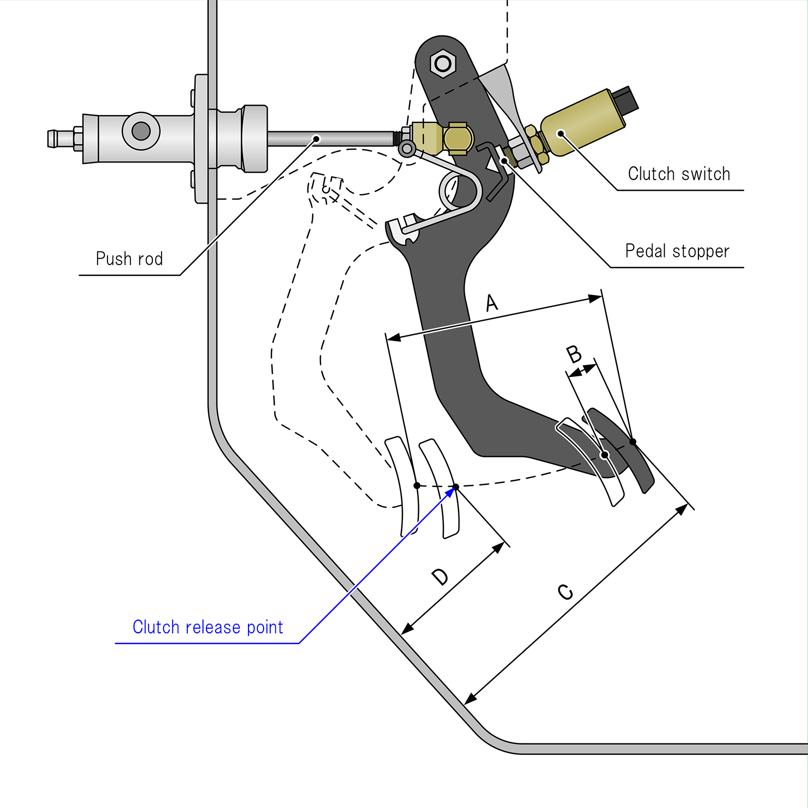
| Measurement point | 1991 Coupe | 1992 NSX-R |
|---|---|---|
| A: Full stroke | 130~135mm | 112mm |
| B: Pedal free play | 9~15mm(※1) | |
| C: Height from the floor | 186.4mm | 164.2mm |
| D: Height from the floor | 92mm or more (*2) | |
*1 Pedal play: 1 to 7 mm
* 2 Height from carpet (reference value): 71mm or more
- If the pushrod is extended too far, pedal play will be reduced, but when the fluid in the hydraulic piping expands due to heat, it will not be able to return to the master cylinder reservoir, resulting in a partially engaged clutch even when the pedal is not depressed.
Since a similar situation can occur if the clutch switch is adjusted too far back, first adjust the pushrod so that the clutch switch is not touching the pedal, and then tighten the clutch switch until it touches the pedal.
The service manual specifies that the clutch switch should be turned in 1/4 to 1/2 turn from the position where it is touching the pedal.
The correct position for the clutch switch is when the pedal is slightly depressed, leaving ample pedal play.
If the coupe pedal is replaced with a damperless system, the clutch stroke shifts the point where the clutch fully disengages, resulting in increased wasted stroke.
Therefore, the NSX-R pedal lowers the pedal position to compensate for the wasted stroke without changing the clutch disengagement position from the fully depressed position.
It is possible to adjust the coupe pedal to a position similar to that of the NSX-R by adjusting the clutch switch and push rod, but the assist spring action changes and you won't get the right feeling.
The assist spring reacts in the direction of pressure when you press the pedal when it's in its standby position, but when you press the pedal slightly and the fulcrum, action point, and spring mounting point become linear, this is the turning point, and from that point on, the force changes to assist the pressure you apply.
Therefore, if you lower the coupe pedal to the same position as the NSX-R, the assist spring will be pushed close to the turning point when the pedal is in its initial position, making the initial pedal pressure too light.
Master cylinder installation
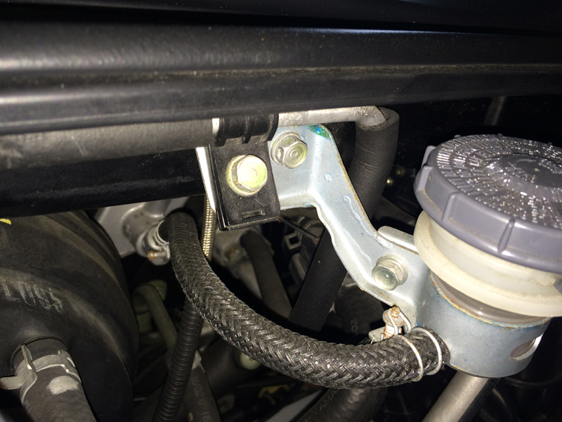
×
![Popup Image]()
RFY conversion clutch line installation
- It would be quite difficult to connect the hydraulic piping between the master cylinder and release cylinder using the original pipes, so we used a RFY conversion clutch line with stainless steel mesh hose.
This product is designed to connect directly to the hose in front of the release cylinder without going through a damper, so it is forced to be damper-less.
We covered it with a corrugated tube to protect it from contact. - Fix the reserve tank bracket to the place where the air conditioning pipe was originally fixed.
Shift the air conditioning pipe bracket to the left and fix it to the reserve tank bracket. - The clutch hose bracket is attached to the damper bracket, not the body, so the damper bracket is used even in a damper-less vehicle.
If you want a smarter installation, we recommend the T3TEC clutch hose bracket, which can be fixed directly to the body ( Clutch Hose Bracket Part Number: T3R-46968open_in_new ) is also an option.

×
![Popup Image]()
Air conditioning pipe bracket
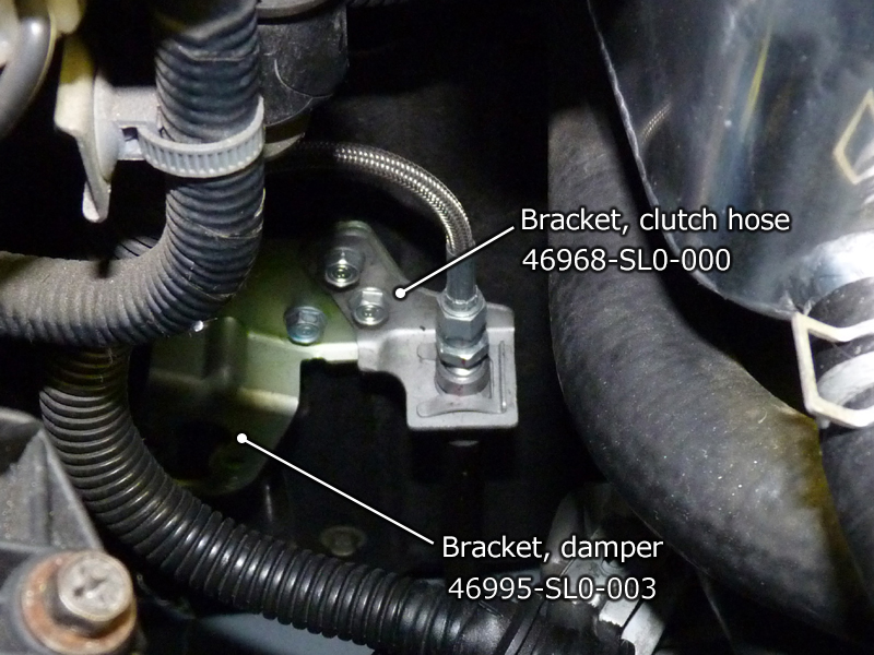
×
![Popup Image]()
Clutch damper part on the engine room side
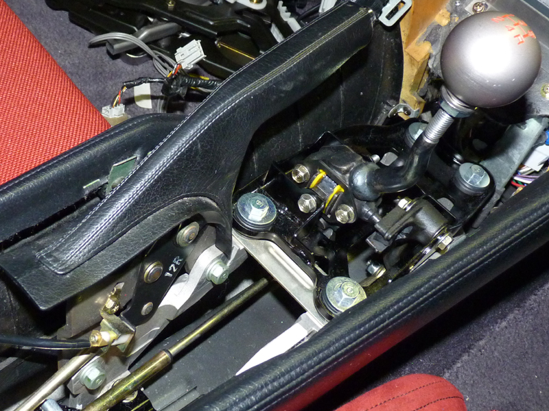
Shift lever installation
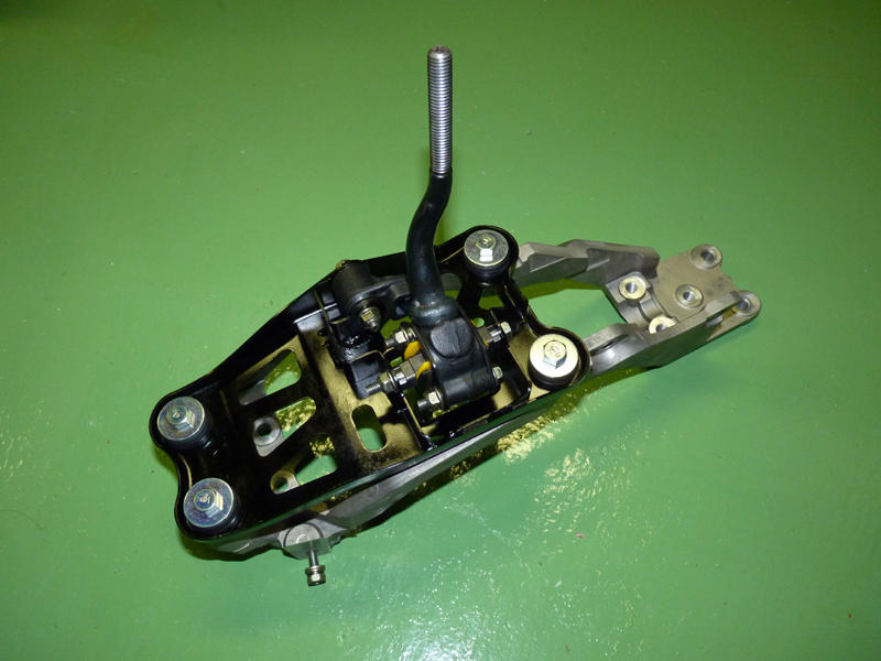
×
![Popup Image]()
MT shift lever assembly
- Apply grease to the moving parts and assemble the shift lever.
The service manual specifies molybdenum disulfide grease, so I used some release grease I had on hand.
The aluminum shift and handbrake base part has a different shape than the one for the AT, so I used the newly purchased one for the MT.
Iron parts such as the shift lever and shift lever bracket are prone to rust in their pure state, so I decided to dye them black.
×
![Popup Image]()
After installing the MT shift lever
- After separating the control wire for the AT and removing the selector lever, the assembled MT shift lever is installed.
The only remaining interior work is to pull in and connect the MT change wire, but once that's done, we can move on to replacing the transmission itself.
For the time being, we installed an aluminum shift knob that is spherical in the style of the 02R and has a 5-speed pattern engraved on it (the shift pattern on the 02R shift knob is engraved in yellow).