warning
The wiring diagram was created based on information from the early NA1 (100 series).
Please note that the information on this wiring diagram differs for models from 1995 onwards and ACURA (left-hand drive models).
The coupler diagram follows the original wiring diagram, with a single line frame indicating a male coupler and a double line frame indicating a female coupler.
The coupler diagram also shows the coupler as seen from the terminal side for both the male and female sides.
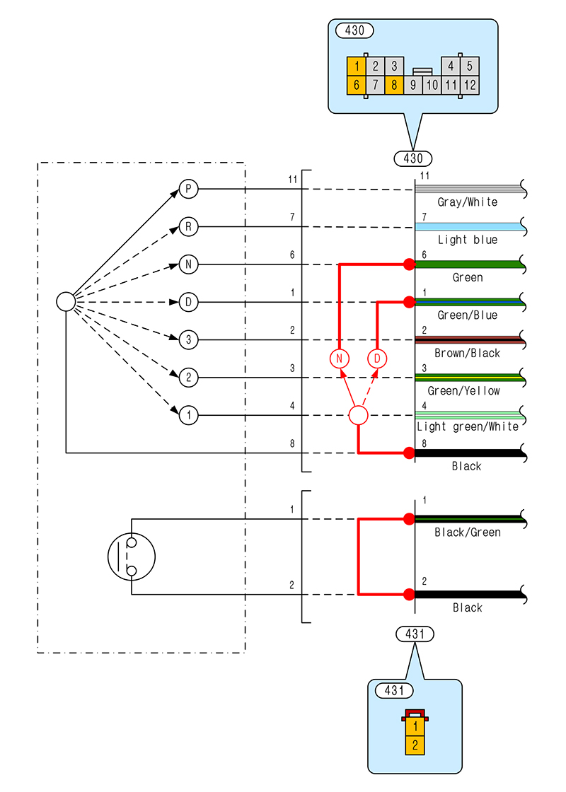
Shift console switch wiring modification diagram
If the ECU remains for an automatic transmission and the automatic transmission selector lever is simply removed, the ECU's neutral signal will not be grounded, resulting in the same condition as when the shift position is in [D]. When the shift position is other than [P] or [N], automatic transmission models increase the amount of air bypass to account for torque converter resistance and control the idle speed to increase. While this control does not cause any problems during normal driving when the shift position is in [D], it can cause issues such as a high, unstable idle that fluctuates, or poor rotational drop when the clutch is released. While there are no issues with idling or normal driving when the shift position is in [P] or [N], the rev limit is set to 7000 rpm, possibly because the system determines that the engine is revving without load, and the system does not switch to VTEC even after warming up (*1, *2).
*1 If the shift position is other than [P], the key lock solenoid will be activated and the key will not be able to be removed.
*2 Regardless of whether the transmission is AT or MT, the conditions for switching to VTEC are a vehicle speed of 5km/h or more and a water temperature of 60°C or more.
In other words, to operate the car normally, you need to switch to [P] or [N] when stopped, and to [D] when the car starts moving.
Connector of the shift console switch section
- The [N] signal is sent to the ECU by shorting the [N] signal and [ground] ([6] and [8] on the [[430]] pin) of the 12-pole coupler. Furthermore, to release the rev limit and VTEC switching restrictions while driving, you need to switch from [N] to [D] after the car has started moving for a while.
- The inhibitor switch is designed so that electricity flows when the shift position is in [P] or [N] and the engine will not start when the shift position is in any other position where electricity does not flow. The engine can be started by shorting the vehicle harness side ([1] and [2] on [[431]]).
The wiring for the backup lights is completely different between AT and MT, so if you leave it as is, he light will not turn on even if you put the gear in reverse. With AT, the light comes on when the shift lever is in [R], but with MT, the light comes on when the backup light switch in the transmission detects that you are in reverse gear. It may seem like you need to run new wiring to turn the light on, but in fact, it can be resolved using a simple wiring method.
- When converting from an automatic to a manual transmission, you will have four extra couplers near the manual transmission. By using one of these, you can easily route the wiring for the backup light switch into the interior.
- We will modify the area around coupler [[33]]. We will short-circuit wire [2] (red/white) for the lock-up control SOL.V and wire [3] (green/black) for the backup light.
- Connect the [7] wire (white/black) for the lockup control SOL.V to the IG power supply. The IG power supply is a yellow wire, and several can be found nearby. I connected the power supply for the TCS that I no longer needed.
No. 33 Coupler (rear of passenger seat)
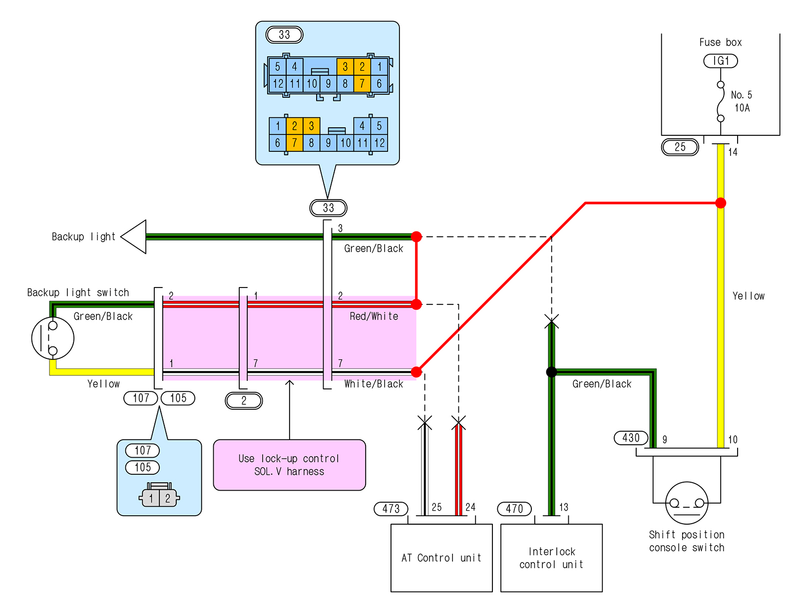
Backup light switch wiring modification diagram
In an AT, when the range is put into [N], a signal is sent to the ECU from the shift console switch, but in a MT, a signal is sent to the ECU from the neutral switch on the transmission itself. However, if the ECU remains for an AT, idling will become unstable when the [N] signal is not input, so it would be problematic if the ECU only judges the gear to be in neutral when it is actually in neutral. For this reason, the signal from the transmission's neutral switch to the ECU is only connected if the ECU is replaced with one for a MT.
There is no wiring for the neutral switch in an automatic transmission, but like the backup light switch, an unused coupler can be used.
- It is pulled into the room using a 3-pole coupler for a "linear solenoid" (a coupler that has 3 poles but only uses 2 poles).
- Connect wire [9] (gray) of coupler [[33]] to the wire (light green) that goes to the ECU via coupler [[4]] and coupler [[154]], and connect wire [8] (black/white) of coupler [[33]] to body earth.
Connector near the ECU
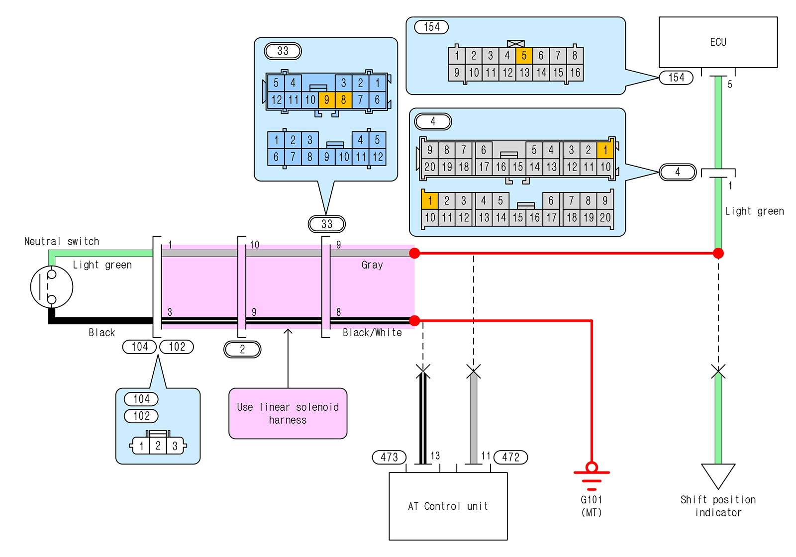
Neutral switch wiring modification diagram
There are two types of clutch switches: a three-pole type for the coupe and a two-pole type for the NSX-R. I wanted to keep the auto-cruise function, so I used the three-pole type for the coupe, which can take signals from two points. One of the two signal wires is connected to the ECU, and the other is connected to the auto-cruise unit. I don't know what role the signal to the ECU plays, but since the clutch switch has an NC contact (*3), I think it has a fail-safe function, such as not switching to VTEC when the clutch is disengaged.
*3 A normally closed contact through which electricity flows when the coil is not energized (a switch that stops electricity flow when the clutch is depressed).
- For automatic transmission vehicles, the wiring to the cruise control unit runs from coupler [[430]] on the shift position console switch to the unit. Connect the NC contact of the clutch switch ([2] on [[416]] if you follow the wiring diagram) to [5] on coupler [[430]].
- In an automatic transmission vehicle, the wiring leading to the ECU is interrupted at the previous coupler [[4]], so a new wire must be run from the NC contact of the clutch switch ([3] of [[416]] if you follow the wiring diagram) to terminal [12] of coupler [[4]].
- Connect the clutch switch ([1] of [[416]]) to earth (the wiring diagram shows it as earth point G401, but any other point will do).
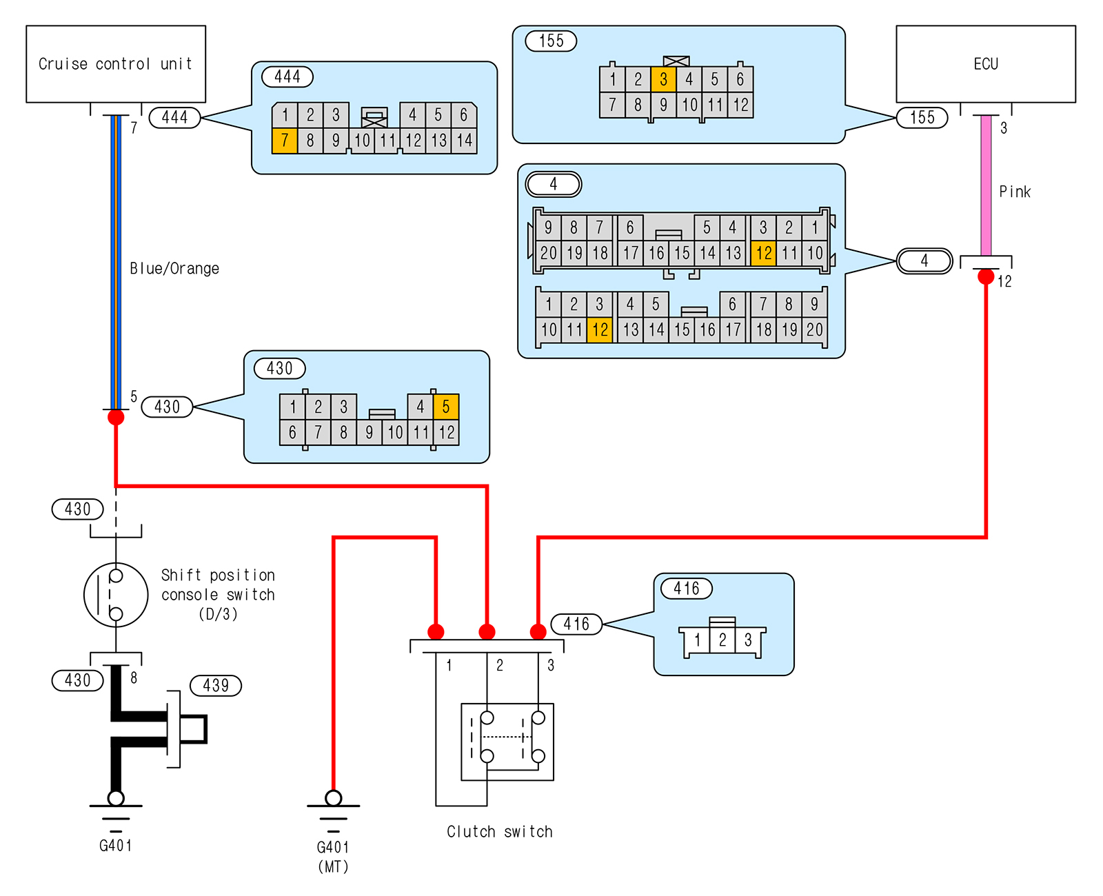
Clutch switch wiring modification diagram
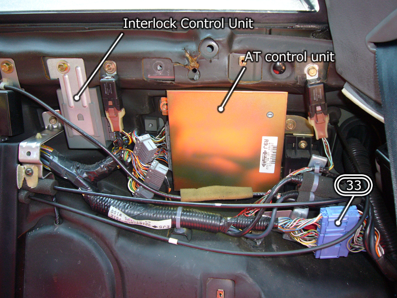
Location of the interlock control unit
- The interlock control unit is fixed to the left of the AT control unit behind the seat. This unit is only installed in AT models and restricts operations related to the shift position, such as preventing the engine from starting if the shift position is not in [P] or [N] and preventing the key from being removed if the shift position is not in [P]. It will be removed as it will no longer be necessary with the conversion to MT.
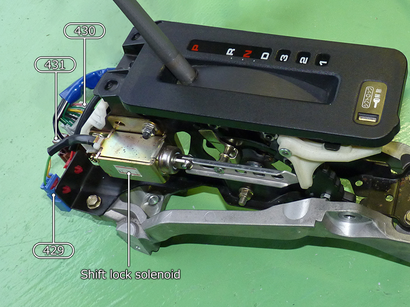
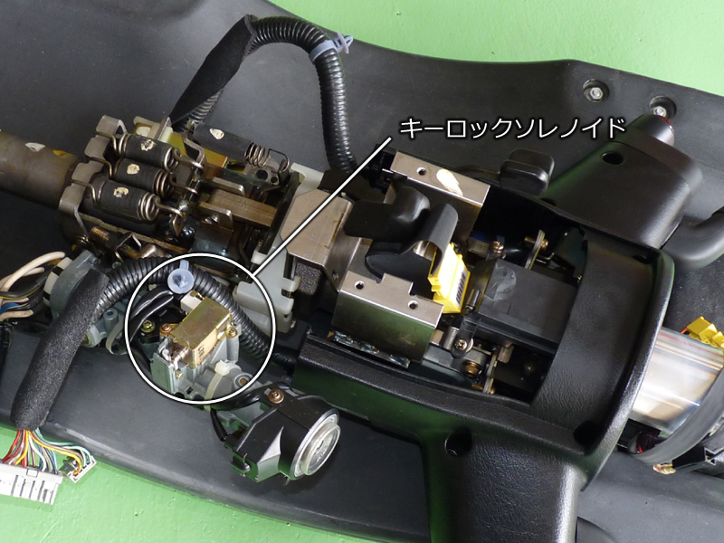
- The key lock solenoid physically locks the key so that it cannot be removed, and is fixed to the underside of the driver's seat key cylinder. If you have other ideas for using it, you can leave it in and use it, but since it is only installed on AT vehicles, we will remove it.
- Removed unnecessary parts. In addition to the interlock control unit and key lock solenoid, we also removed the reverse chime (the chime that sounds when the shift position is put into reverse) that was attached to the back of the cover under the steering column.
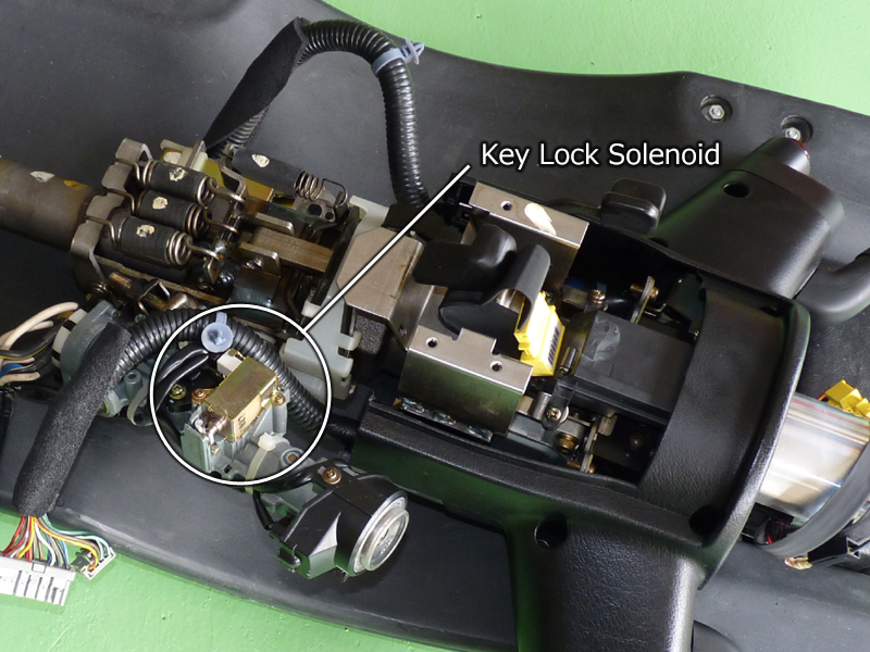
Location of the key lock solenoid
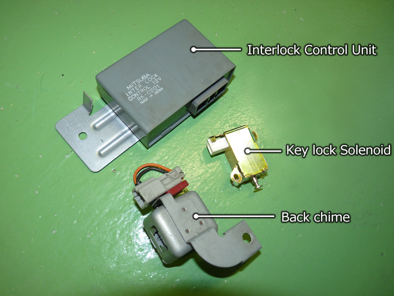
Parts removed due to manual transmission