When converting to a manual transmission, I wanted to remove everything unnecessary. However, the AT computer converts the signal from the NC speed sensor into pulses and sends them to the EPS unit.
The EPS unit controls the power steering by comparing the vehicle speed signal from the main speed sensor (VSS1) with the signal from the NC speed sensor (VSS2), which counts the teeth of the ring gear for power steering control.
Although the NC speed sensor (VSS2) signal is only auxiliary, if it is lost the system judges it as an error, the EPS check light will turn on, and the power steering will no longer function after the engine is restarted.
If the pulses from the main speed sensor (VSS1) and those output via the AT computer from the NC speed sensor (VSS2) are of the same specification, it may be possible to resolve the issue by splitting the VSS1 pulse and feeding it into the EPS unit.
Therefore, I compared the pulses from both with an oscilloscope.
- I used a PC-connected oscilloscope. This product is a DIY kit, but it can be made in about an hour and is reasonably priced for a PC-connected oscilloscope. I bought it from a website called "Kamihikoki" and it is now called Cokky netopen_in_new .
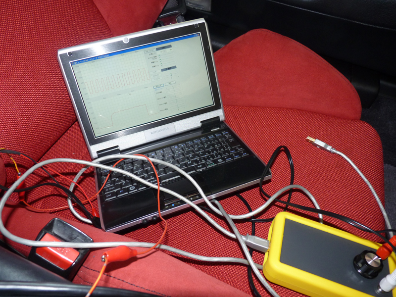
Use a PC-connected oscilloscope
AT computer vs. main speed sensor waveforms
- The top row shows the output waveform from the AT computer, and the bottom row shows the output waveform from the main speed sensor. The AT computer produces about 7 pulses for every 1 main pulse. If the main signal is branched and used, it would need to be converted to 7 times the pulse size, which is not a practical solution.
NC speed sensor output waveform
- Next, I tested the signal from the NC speed sensor. It showed a sine wave waveform (a swing of more than ±25V when tested at low speeds). When using an NC speed sensor, this sine wave must be converted to a 4.5V pulse. Starting with the 110 model, which allows manual transmission vehicles to be equipped with power steering as an option, adding power steering to a manual transmission vehicle comes with a pulse unit to convert the output of the NC speed sensor into a pulse. While using this pulse unit is the easiest solution, I decided to explore other options.
| Part Number | Part Name | Unit price | Remarks |
|---|---|---|---|
| 39985-SL0-951 | Pulsar Unit | 14,100 | As of December 2010 |
To convert the sine wave of ±25V or more output from the NC speed sensor into a +5V pulse, one method is to use a constant voltage circuit with a Zener diode to cut off voltages below 0V and above 5V.
- However, the sine wave from the speed sensor has the characteristic that at low speeds it has a weak voltage and a wide wave width, but as the speed increases the voltage increases and the wave width narrows, so simply cutting off voltages below 0V and above 5V may not be enough to recognize it as a signal, and some countermeasures are necessary. To do this, we use a comparator (a type of operational amplifier) that outputs 5V when the input turns positive.
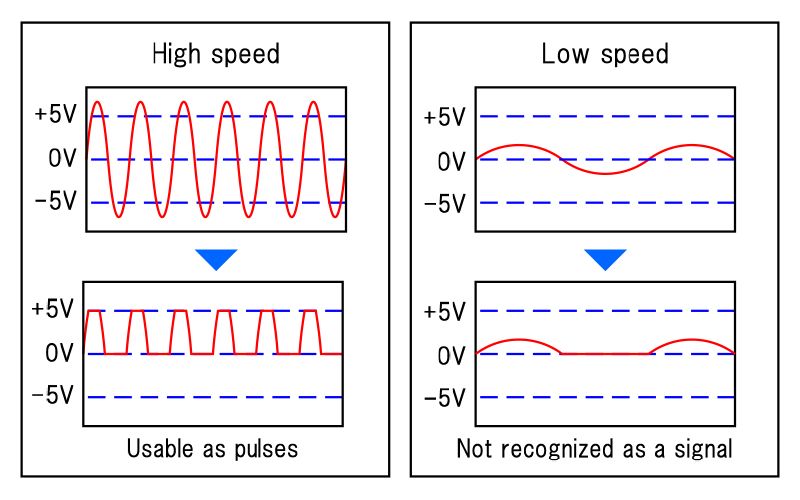
Sine wave difference at low and high speeds
I purchased the necessary components from well-known online electronics retailers, RS Componentsopen_in_new and Akizuki denshiopen_in_new .
* Note that some components cannot be purchased individually.
| Name | Specification | Unit price |
|---|---|---|
| PolySwitch | RXEF07 0.75A | 43 |
| Schottky barrier diode | SB160-E3/54 1A 60V | 15 |
| Zener diode | BZX79-C4V7 4.7V 500mW | 10 |
| ceramic capacitors | 50V 100000pF | 60 |
| Aluminum electrolytic cap | 105℃ 25V 470uF | 70 |
| Aluminum electrolytic cap | 85℃ 25V 10uF | 20 |
| Potentiometer | CT-6EP 10kΩ 0.5W 10kΩ | 150 |
| transistor | 2SC1815-Y(F) NPN | 14 |
| 3-terminal regulator | NJM7805FA 5.0V 1.5A | 90 |
| Operational Amplifiers | LMC6482 | 186 |
| Carbon Resistor | 1/4W 1kΩ | 1 |
| Carbon Resistor | 1/4W 10kΩ | 1 |
| Carbon Resistor | 1/4W 4.7kΩ | 1 |
| Total amount | JPY 661 | |
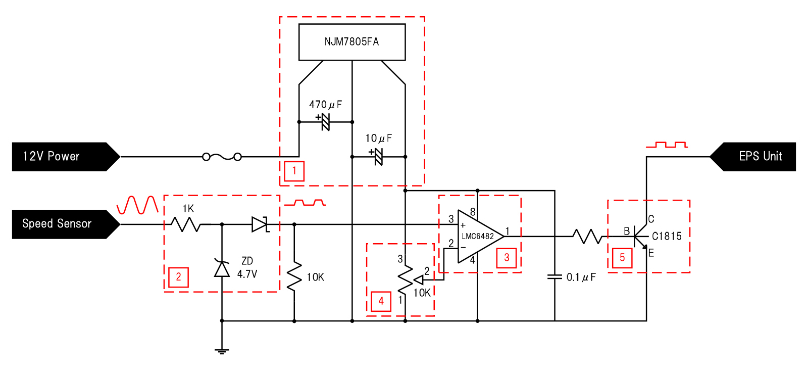
1Step-Down Circuit Using 3-Terminal Regulator
A three-terminal regulator is used to step down 12V to 5V for the circuit power supply. A smoothing capacitor must be placed on the input side, and a stabilizing capacitor on the output side.
The capacitors selected were 470uF for the input side and 10uF for the output side, prioritizing implementation size (according to online information, 470-1000uF is recommended for the input side, and 10-100uF for the output side).
Oscillation was not observed even without the anti-oscillation capacitor, so it was omitted (online information recommends installing a 0.1-0.3μF capacitor).
2Constant voltage circuit using Zener diode
This is a constant voltage circuit that connects a diode in the opposite direction to the input and uses the diode's breakdown voltage.
Electricity flows normally up to the breakdown voltage (4.7V in this case), and when it exceeds 4.7V, the diode enters a breakdown state and electricity flows to the ground side.
In addition, a Schottky barrier diode rectifies only the positive side, cutting off sine wave voltages below 0V and above 4.7V.
3Comparator-based amplifier circuit
A comparator (LMC6482) with a reference voltage set to around 0V is used so that a 5V output can be obtained when the input to the amplifier circuit using three comparators
is slightly above 0V.
This ensures that the output is exactly 5V even when the voltage is low at low speeds.
4Comparator hysteresis adjustment circuit
If the output from the comparator becomes Hi the moment the input exceeds 0V, it will react to even the slightest noise, so we will use a threshold setting circuit using a potentiometer to adjust the minimum voltage at which it will react.
5Switching circuits using transistors
The output of the comparator takes a little time to rise to 5V, and when viewed on an oscilloscope it appears as a trapezoidal waveform.
By amplifying it using a transistor, it is adjusted to a pulse that rises vertically.
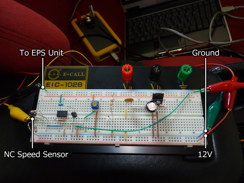
Testing prototype circuits on a breadboard
- The circuit was prototyped on a breadboard. A breadboard is a prototyping tool that allows you to create circuits simply by inserting electronic components. Connect the input from the NC speed sensor, the output to the EPS unit, the power supply (12V), and the ground. The other wire from the NC speed sensor was connected to the ground. When I started the engine and performed a test run, there were no EPS errors and it worked without any problems.
- I also checked the waveform with an oscilloscope, and the results were as expected, so there seemed to be no problems. The op-amp used this time has an input threshold of approximately 0.2V, so it cannot detect signals at ultra-low speeds of less than 5km/h. In contrast, the genuine AT control unit produces a pulse output even at ultra-low speeds. There seems to be no problem with operating the EPS unit without error, but it is an area I would like to improve in the future (but as an amateur, I don't know what to do...).
Sine-to-Pulse Converter Output
MSine-to-pulse converter board layout
- To implement the circuit, I built it on a universal board.
After much deliberation, I came up with the most compact layout possible.
I installed the potentiometer with the intention of using it to adjust the comparator's hysteresis (*), but since the op-amp only recognizes it as being at 0.2V or higher, it ended up being a useless component.
* If the output becomes Hi the moment it exceeds 0V, it will react to even the slightest noise, so you need to adjust the minimum voltage at which it reacts.
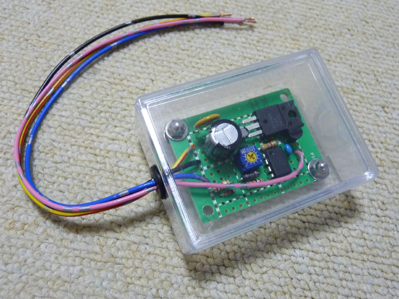
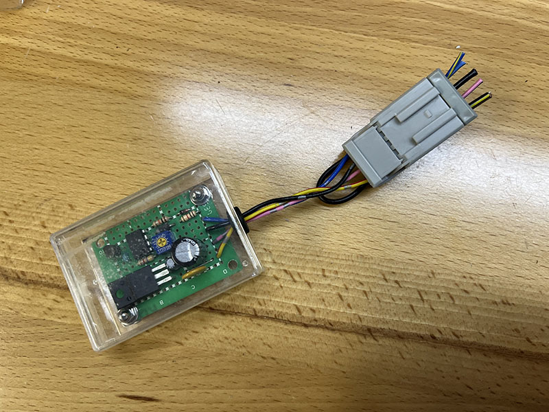
Mounting board stored in a plastic box
- I was worried about a short circuit if I left the circuit board as it was, so I modified a plastic box I had nearby to store it in.
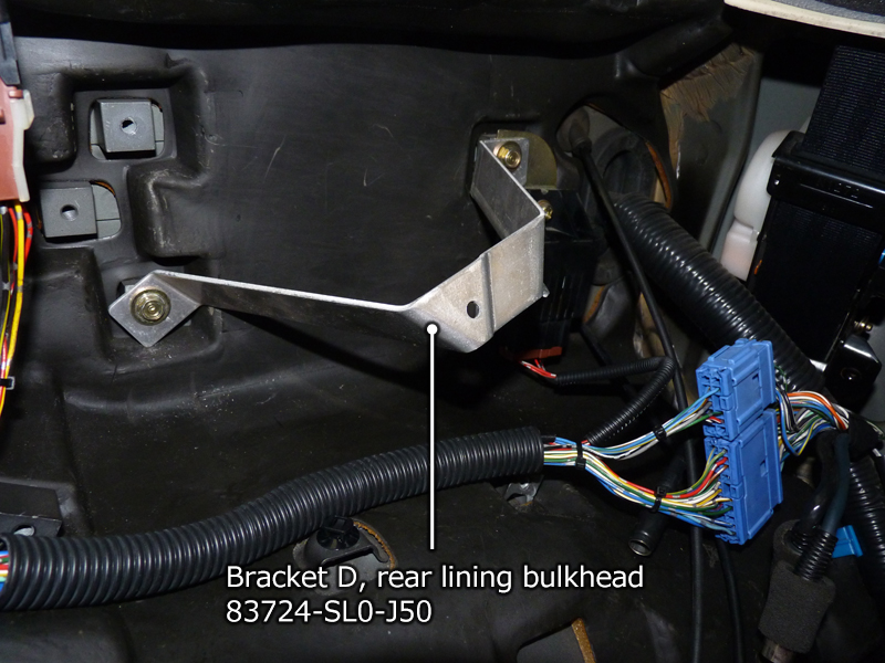
NSX-R bracket (83724-SL0-J50) installed
- The TRC unit has a bracket that fits into the interior panel's fixing clip, so removing the unit would mean one of the clips would no longer be able to be fixed. The NSX-R, which does not have a TRC unit or AT control unit, has a dedicated bracket, so we installed that and were done. It also looks much neater. We wanted to install it when we removed the TRC unit, but since it could not be installed without also removing the AT control unit, we stored it until the removal was complete.
| Part Number | Part Name | Unit price |
|---|---|---|
| 83724-SL0-J50 | Bracket D, rear lining bulkhead | ¥4,200 |
Prices are as of April 2025
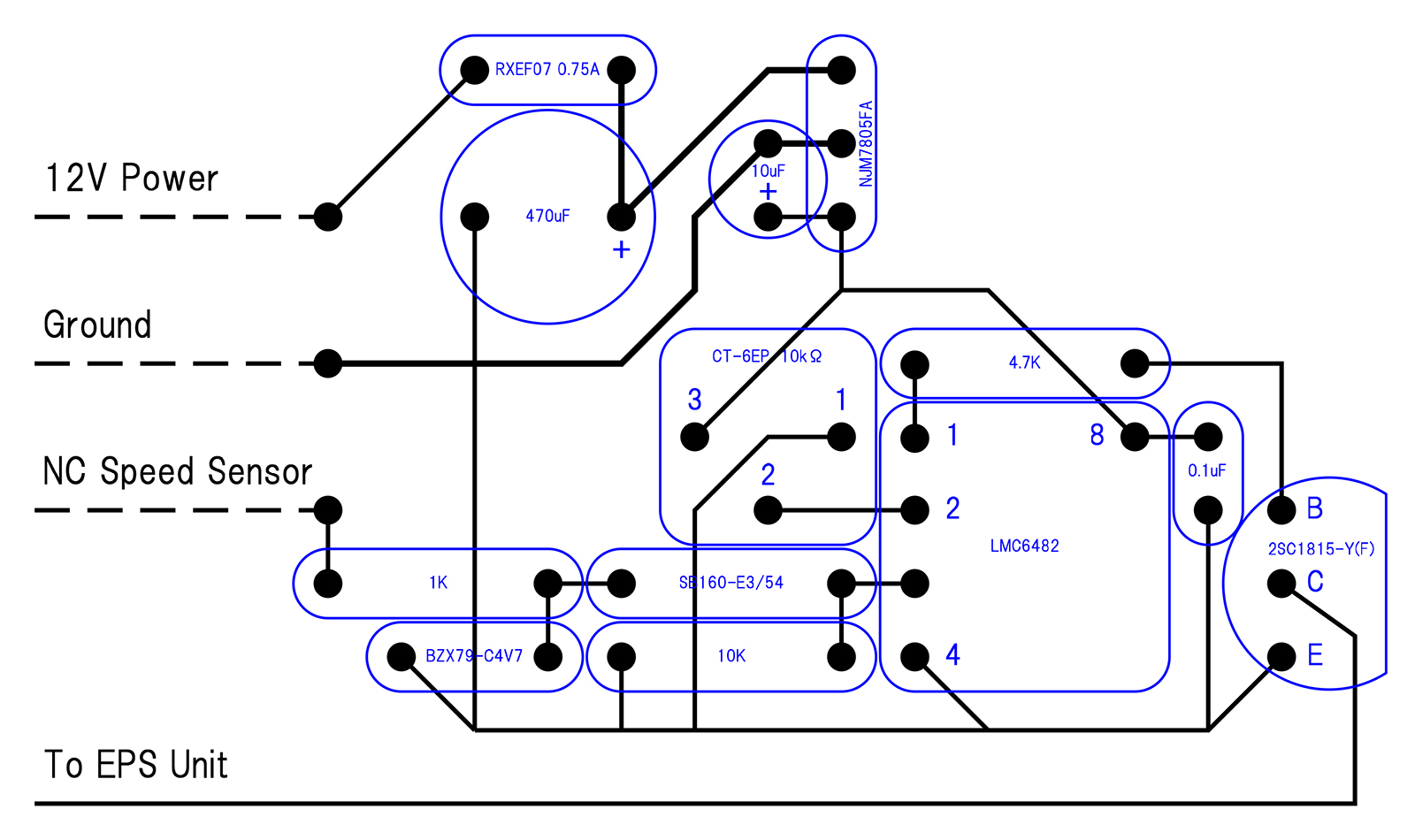
Pattern design with Visio
- Since I had the chance, I wanted to make a complete product, so I decided to fabricate a custom PCB using CNC milling on copper-clad laminate. First, I used Visio to design the cutting diagram. I set the pattern width to 1mm.
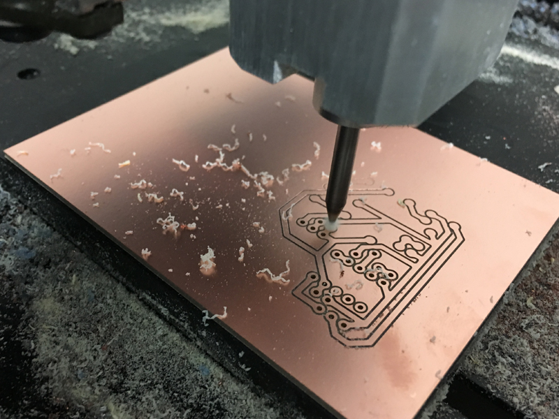
Cutting the circuit board pattern with CNC
- Cutting was done using CNC. The cutting was done in three steps: "pattern cutting" → "hole drilling" → "external cutout". An end mill with a diameter of 0.4 was used.
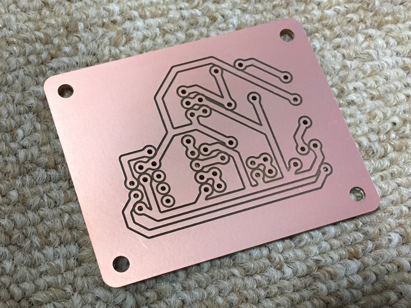
The completed board
- The finished circuit board. It looks like the real thing.
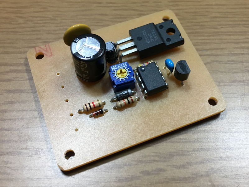
Mounting components on the board
- Although I tried to install the parts, the size ended up being not much different from when using a universal board, so I ended up not using it and just put it away.
I had been using a homemade pulse unit for a long time, but one day I wondered if it was still possible to buy a new one.
When I checked, I found that it had already been discontinued, as expected.
I saw that some second-hand ones were still available on eBay. Since I had been planning to replace it with a genuine one eventually, I decided to secure one before they disappeared and purchased it.
Since EPS assist shutdown due to an error is applied only after the engine is restarted, there is a workaround where you can prevent the warning light from turning on and have the error cleared each time the ignition key is turned off by not connecting the wiring to the warning lamp and backup power to the EPS unit.
However, I wanted to keep the system as close to the genuine state as possible, so I decided to make the final specification a conversion using the genuine pulse unit.
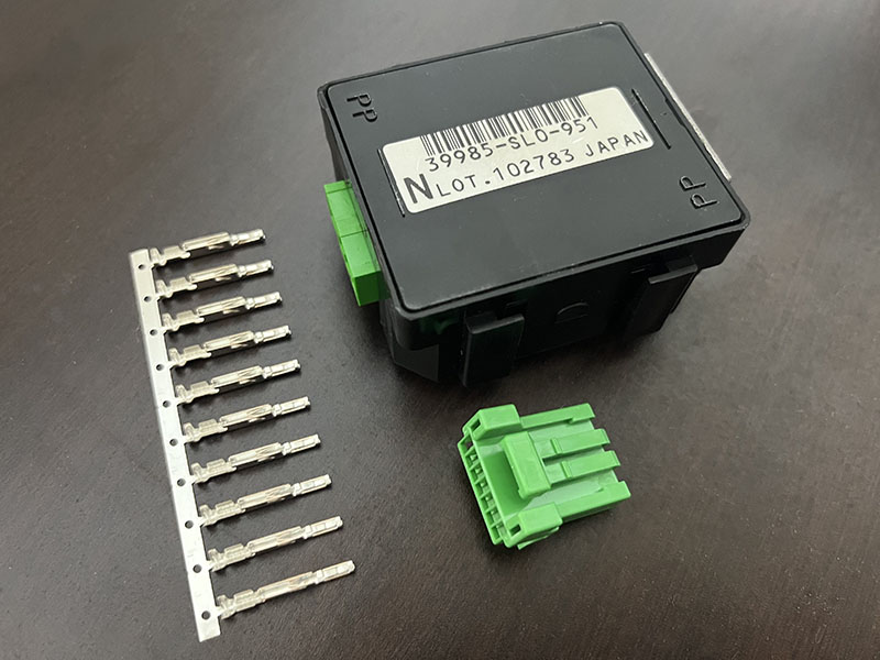
- Genuine pulse unit and purchased connector and terminal.
The pulse unit was purchased on eBay for US$78.85 (※), and the connector and terminal were purchased from Wiring Com.open_in_new
I purchased it at.
* Purchase price: US$57.85 + US$21.00 for shipping.
Total paid: ¥12,282 via PayPal (as of March 18, 2025).
Genuine pulse unit and purchased connector
| name | Model | Unit price | Quantity | Price |
|---|---|---|---|---|
| JAE 025 type IL-AG5 series 7-pole F connector | 7P025-IL-AG5-JAE-F-tropen_in_new | 230 | 1 | JPY 230 |
| JAE 025 type IL-AG5 series F terminal | F025-IL-AG5-JAEopen_in_new | 35 | 6 | JPY 210 |
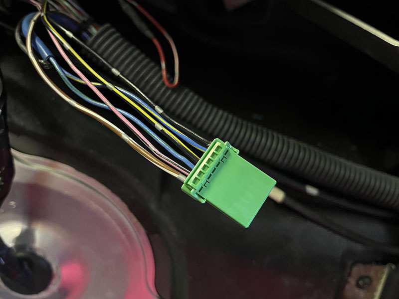
Pulse unit connector processing completed
- The connector is now complete. The power (black/yellow) and ground (black) wires are thick and a little tight on the connector, but I was able to insert them just fine.
- The genuine pulse unit has been installed. I don't know where it was originally attached, but I installed it above and to the left of where the AT control unit was originally located (to the left of the fuel pump relay).
- The removed homemade pulse unit. After examining past photos, I found that this homemade pulse unit had been in use since August 2013, and had been functioning without any problems for a long period of 11 years and 8 months, up until April 2025.
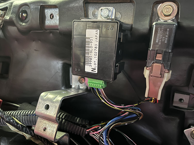
Genuine pulse unit installation complete
Removed homemade pulse unit
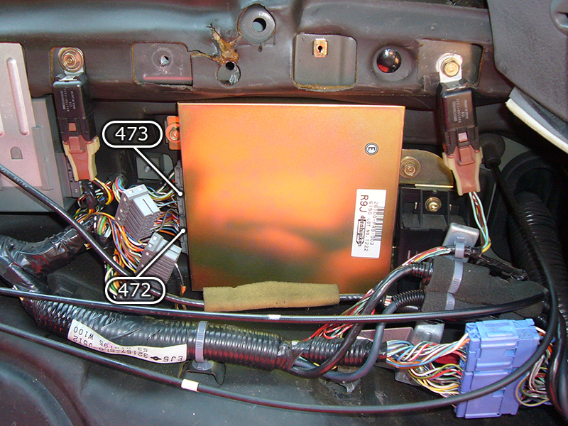
AT control unit connector
- AT control unit connector. In my case, I had installed a homemade pulse unit, so the wiring was already organized, but normally you would need to modify the wiring of the connector that plugs into the AT control unit.
- I'm not sure if anyone else is looking to remove the AT control unit in order to achieve a fully manual transmission, but I created a wiring diagram for when you replace the AT control unit. As shown in the wiring diagram, you can replace the factory pulse unit using only the wiring included in the [[472]] and [[473]] connectors that are plugged into the AT control unit. You'll have to use the signal wires as they are, but the power and ground wires are a little thicker than the connector for the pulse unit, so I think it's fine to bring them from somewhere else.
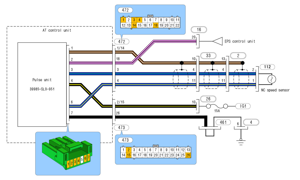
AT control unit to pulse conversion diagram