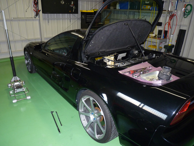
Space on both sides of the vehicle
- The removed automatic transmission will be removed from the passenger side, so park your car with plenty of space on that side. As long as you have enough space for the transmission itself, you should be able to work in a single-car garage, but in my case, it's a two-car garage with a sliding central pillar that opens up the entire garage, so I parked my car right in the middle. First, you'll need a rigid rack with a certain height. With the rigid rack I used, I was able to remove and install the transmission at the lowest position it could be secured with pins (about 40cm high). First, remove the air cleaner box, which gets in the way. Removing the air cleaner box exposes the automatic transmission itself, so remove all wiring, including the coupler connected to the automatic transmission sensors and the starter motor power terminal.
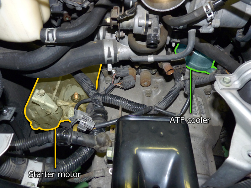
Starter and ATF cooler
- Remove the three bolts accessible from above: the two bolts securing the transmission to the engine, and the one bolt securing the starter. The starter cannot be removed from below without removing the member, so remove the remaining securing bolt from the bottom and remove the starter from above. The automatic transmission is equipped with an ATF cooler to which two coolant hoses are connected, so disconnect those first. Since this piping will be bypassed after the manual transmission conversion, the hoses will not be reused, and the space was tight, making it difficult to work, so I cut them with a cutter. This completes what can be done from the top, leaving only the separation of the transmission mount.
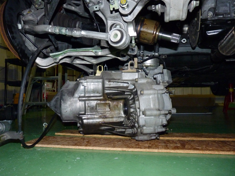
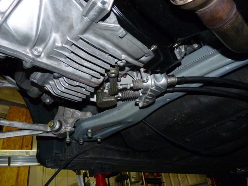
Select and shift cable installation complete
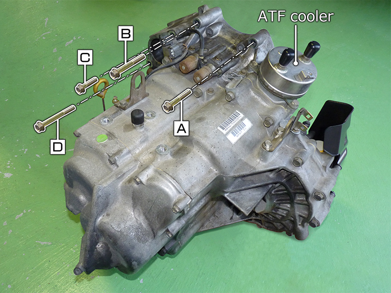
- Since the bolt locations and structure are difficult to see when the automatic transmission is installed in the vehicle, we will provide additional explanations using a photo of the removed automatic transmission. [A] and [B] are the transmission fixing bolts, which are removed from above. These bolts are hidden under the water passage and difficult to see, so you will need to feel around to loosen them. [C] is the bolt that secures the starter to the transmission (removed from above), and [D] is the bolt that passes through the transmission and secures the starter to the engine (removed from below). There are a total of six transmission fixing bolts, four of which are different lengths for automatic and manual transmissions (see the table below). The ATF cooler is a cylindrical part with nipples for connecting two coolant hoses (rubber caps are attached to the nipples in the photo). This nipple connects to a nipple in the water passage, which is only available on automatic transmission vehicles, and to a nipple on the cooler connecting case below the engine.
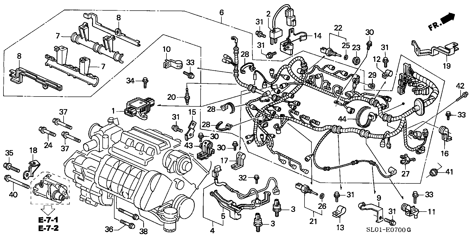
List of transmission fixing bolts
| Where used | Parts Drawing Number | Transmission Type | Part Number | Part Name |
|---|---|---|---|---|
| {A} | 24 | AT | 90051-PE0-000 | Bolt, flange 12x70 | MT | 95701-1206508 | Bolt, flange 12x65 |
| {B}{E} | 37 | AT | 95701-1210008 | Bolt, flange 12x100 | MT | 95701-1206508 | Bolt, flange 12x65 |
| {C} | 35 | AT | 95701-1203808 | Bolt, flange 12x38 | MT |
| {D} | 40 | AT | 95701-1214008 | Bolt, flange 12x140 | MT | 95701-1211508 | Bolt, flange 12x115 |
| {F} | 38 | AT | 95701-1208008 | Bolt, flange 12x80 | MT |
| {G} | 36 | AT | 95701-1204508 | Bolt, flange 12x45 | MT |
Transmission fixing bolt diagram
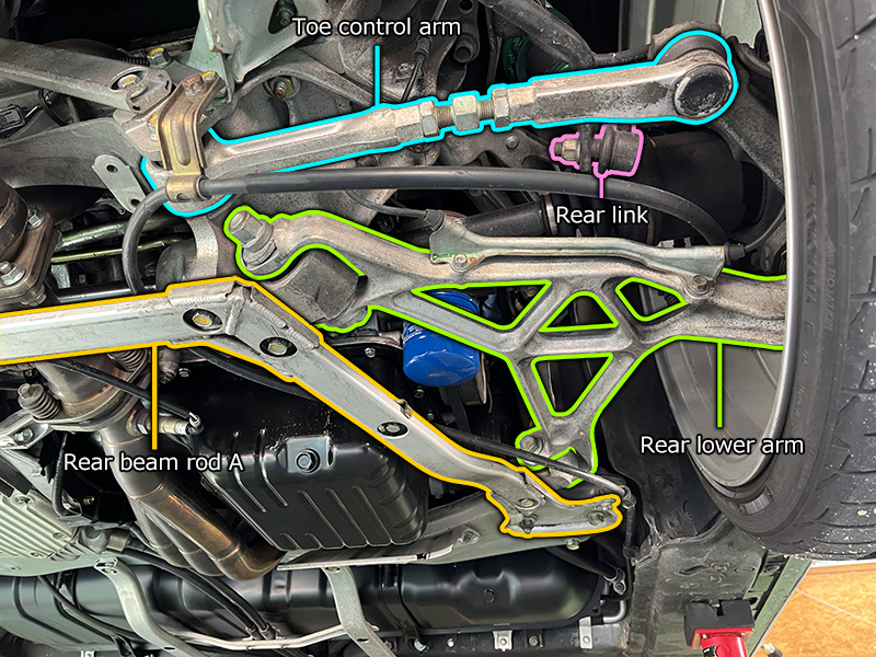
Separate suspension arms
- Separate the suspension arms to remove the drive shaft. You don't need to remove the arms completely, just separate one side so that the knuckle moves outward enough to remove the drive shaft.
- Remove the U-shaped reinforcement bar (rear beam rod A) that connects the front beam and rear beam.
- Remove the bolt nuts on the beam side of the rear lower arm and toe control arm, and the nuts securing the stabilizer link (rear link) and stabilizer bar.
The lower arm has an eccentric bolt, so mark it for reinstallation.
The stabilizer link bolt is an integrated ball joint, so insert a hex wrench into the hole at the end of the bolt to hold it in place so it doesn't rotate, then loosen the nut. Once the upper arm, lower arm, and stabilizer link are separated, you should be able to slide it outward enough to pull out the driveshaft.
- Pull the left and right driveshafts out of the transmission. On the right side (driver's side), first remove the connection to the half shaft, not the transmission itself. This connection is male on the half shaft side, and the shaft's insertion length is short, so it can be pulled out relatively easily by just prying it with a flathead screwdriver or similar. (Pulling on the knuckle side of the driveshaft will only stretch it, so pry it out by prying at the base on the transmission side.) It will be easier to pull out if you use a garage jack or similar to lift the knuckle and help keep the driveshaft horizontal. The left side (passenger's side) has a longer shaft insertion length than the right side (driver's side), so the horizontal sliding distance is larger and it is more difficult to pull out. If sliding is difficult, separating the lower end of the damper from the knuckle will give you a little more space to slide it.
- Pull out the half shaft on the right side (driver's side). Simply removing the bracket fixing bolts will not allow you to remove it as it will interfere with the surrounding area, so you need to remove the bolts that secure the bracket to the shaft and then slide out just the shaft. The shaft is firmly attached to the bracket so it won't move at all with just a little force. After spraying lubricant and heating the bracket with a heat gun, I was able to pull it out. Finally, drain the ATF.
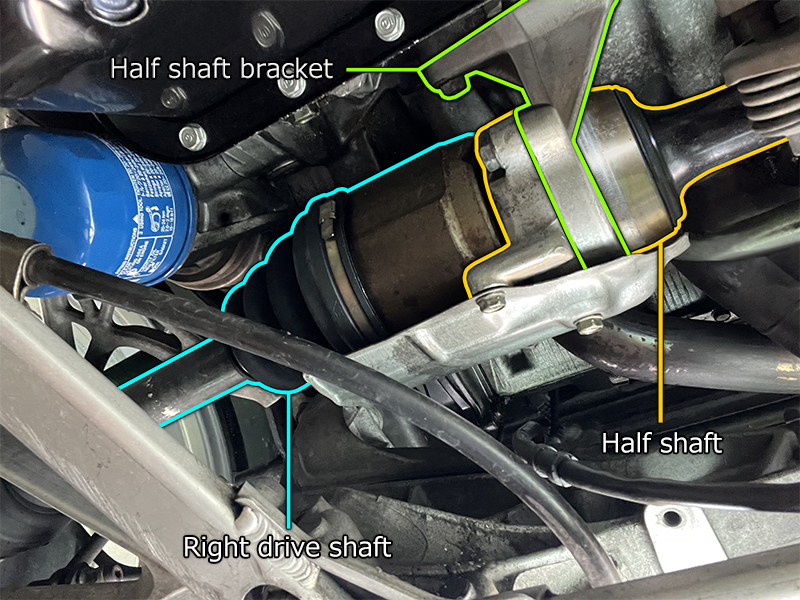
Half shaft connection
- The drive shaft is inserted into the transmission body on the left side (passenger side), while the drive shaft on the right side is connected to a half shaft inserted into the transmission body.
- The correct way to lower a transmission is to hang it from above with a chain block, but we don't have the equipment to do so. An automatic transmission is significantly heavier than a manual one and weighs roughly 80 kg. I couldn't imagine getting under the car and lowering it while supporting it myself, so I decided to use an engine holder and lever hoist, which is an unconventional method. To lower the transmission, the front and rear engine mounts must be separated. However, if they were completely separated, the engine would only be held in place by the side engine mount on the right side (driver's side), so the engine itself must also be suspended by a chain.
*This is an irregular method, so if you do it the same way, do so at your own risk.
Remove transmission using engine holder
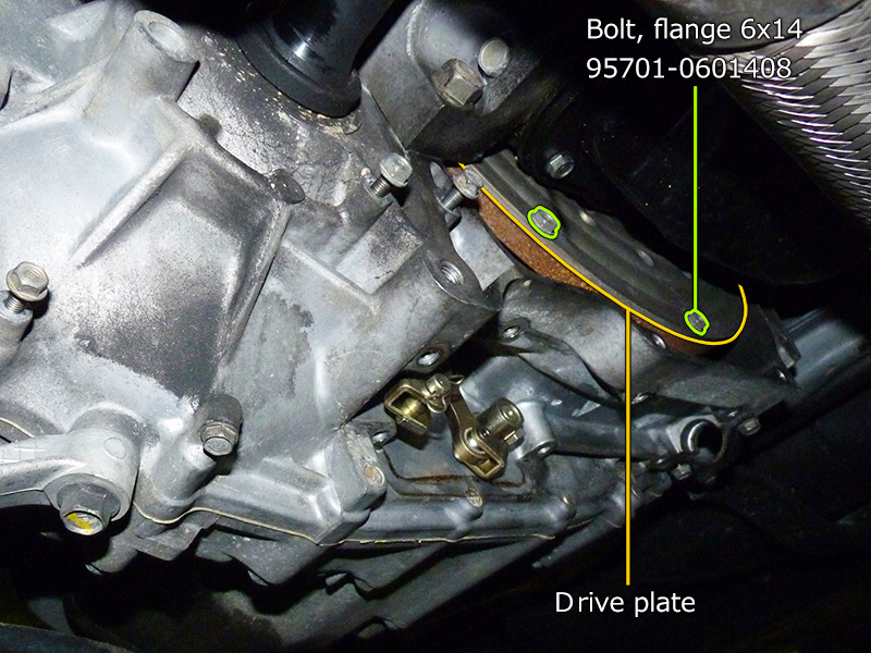
Remove the drive plate fixing bolts
- The drive plate will be exposed when you remove the plate (torque converter case cover) that covers the bottom of the transmission. The drive plate is secured to the torque converter with eight M6 bolts on the outer periphery. Only a small portion of the bottom side of the drive plate is exposed, so rotate the crank and remove the securing bolts around the entire periphery to separate the drive plate from the torque converter. Also remove the shift control wire.
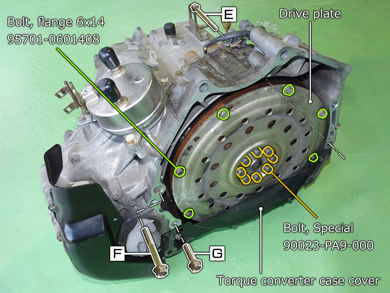
Drive plates, torque converter case covers
- Since it is difficult to understand the structure when it is installed in the vehicle, we will provide a supplementary explanation using a photo of the automatic transmission removed. The photo shows the drive plate and torque converter case cover that were removed when removing the transmission, re-fastened. The drive plate is connected to the torque converter with eight M6 bolts on the outer periphery. This is the part that is exposed when the drive plate is installed in the vehicle. The eight special bolts in the center of the drive plate are 12-point bolts specific to ATs that secure the drive plate and crankshaft, which are removed after the transmission is removed.
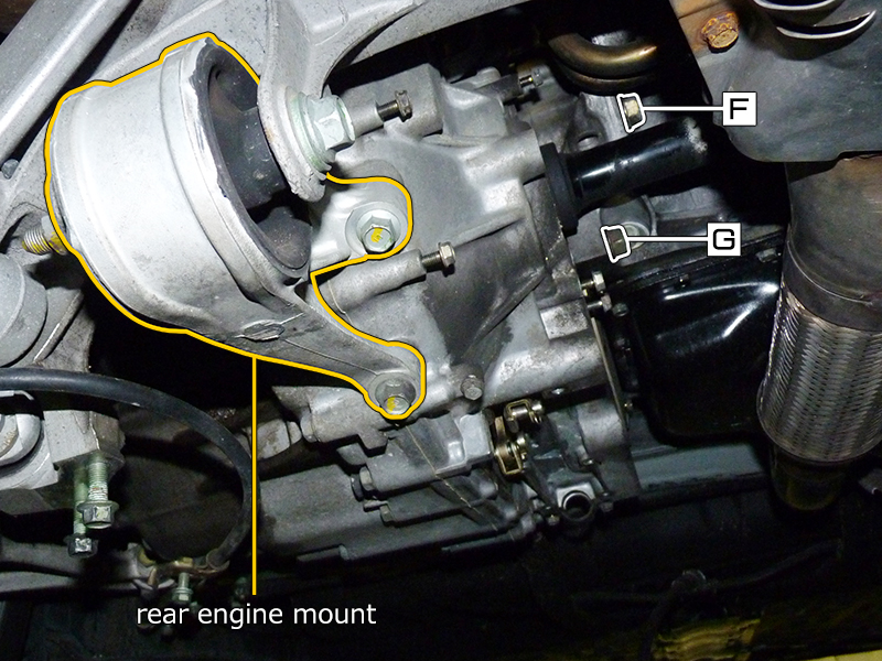
Lower transmission bolt, rear engine mount
- Separate the front engine mount (rubber assembly) and rear engine mount (rubber, rear engine mounting). After separating the front and rear engine mounts, the engine will only be held in place by the right-side (driver's side) side engine mount, so some method of supporting the engine itself is required. In this example, an engine holder is used to support the engine with a chain. After removing the remaining three lower bolts securing the engine and transmission, the transmission will now be held in place only by the upper transmission mount (rubber, transmission mounting). [E] (see photo {08} ) is the bolt attached from the transmission side, slightly below the lower starter fixing bolt. [F] and [G] are the bolts securing the rear of the transmission from the engine side.

Automatic transmission removal complete
- Once you remove the transmission mount fixing bolts from above and separate it, the automatic transmission will be connected to the engine only by a knock pin. Shaking the transmission and shifting it slightly outward will easily separate it, and then all you have to do is lower the lever hoist. I purchased a lever hoist to save money, but when we actually performed the work, we found that it was not suitable for work like this (※1). Finally, remove the eight bolts securing the drive plate to the crankshaft and remove the drive plate. These fixing bolts are 17mm 12-point bolts, so a 12-point socket is required. There are special tools available, but a regular 12-point socket worked fine.
*1 With a lever hoist, you feel as if the brake is released for a moment every time you swing the lever, and although it is actually held in place by a claw, you don't feel a sense of security. It only lowers gradually, making it difficult to make fine adjustments up and down. Furthermore, when you finish lowering the load and want to release it, if there is even a small amount of load on the chain, it will not enter "idling mode," so you must completely lower the load to release the tension.
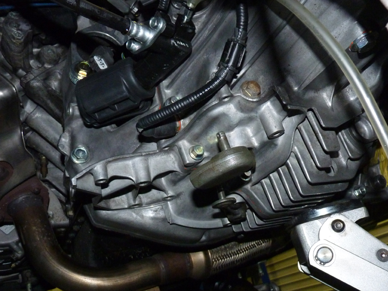
Bypassed ATF cooler hose
- In automatic transmission vehicles, the ATF cooler is arranged between the water passage and the cooler connecting case. Manual transmission vehicles, which do not have an ATF cooler, use a water passage and cooler connecting case that do not have nipples for this piping. This time, we chose to bypass it with a hose, prioritizing cost. We used a φ13 general-purpose silicone hose.

Cooler Connecting Case 19425-PR7-A00
- The Water Passage was expensive, so I just bought an inexpensive cooler connecting case and stored it for the time being. I had hoped to purchase the Water Passage and eventually make it the same specifications as the MT, but sales of the Water Passage were discontinued in June 2024, so I was forced to give up on my dream of recreating the perfect MT specification.
Price at purchase (January 2010)
| No | Part Number | Part Name | unit price | quantity | price | remarks |
|---|---|---|---|---|---|---|
| 4 | 19425-PR7-A00 | Case COMP., Cooler connecting | ¥10,285 | 1 | ¥10,285 | |
| 6 | 19410-PR7-A00 | Passage Comp., Water | (59,400) | 1 | Sales end June 2024 | |
| Total amount | ¥10,285 | |||||
All prices shown are exclusive of tax.
Loading...
| No | Part Number | Part Name | unit price | quantity | price | remarks |
|---|---|---|---|---|---|---|
| 4 | 19425-PR7-A00 | Case COMP., Cooler connecting | 1 | |||
| 6 | 19410-PR7-A00 | Passage Comp., Water | 1 | Sales end June 2024 | ||
| Total amount | ¥0 | |||||
All prices shown include tax.
*Parts with blank unit prices are either out of production or unavailable for order at the time of the survey.
*Even if a part has a unit price displayed, it may no longer be in production.

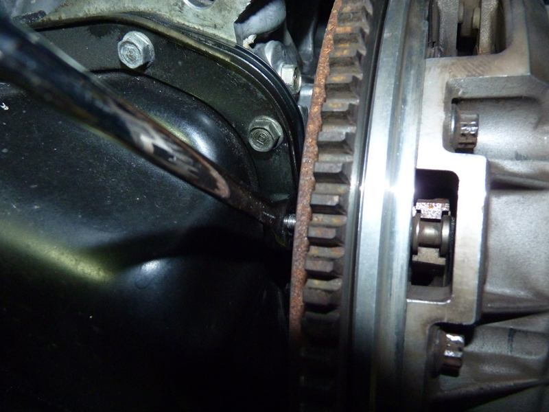
Before installing the flywheel
- Before installing the flywheel, the rear end of the crankshaft is visible.
- After installing the pilot bearing (91006-PR7-008) into the flywheel, install the eight fixing bolts to secure the flywheel. The fixing bolts are 12-point bolts specifically for manual transmissions, which are different from the bolts that come with automatic transmissions. You will need the same 12mm 12-point socket as for automatic transmissions. build Flywheel fixing bolt torque: 10.5 kg-m
- Before installing the clutch, make sure that the damper spring and spring collar are installed on the flywheel. The damper spring should be installed with the raised part in the center facing forward, and the spring collar should be installed with the groove facing outward.
Tighten flywheel bolts to specified torque
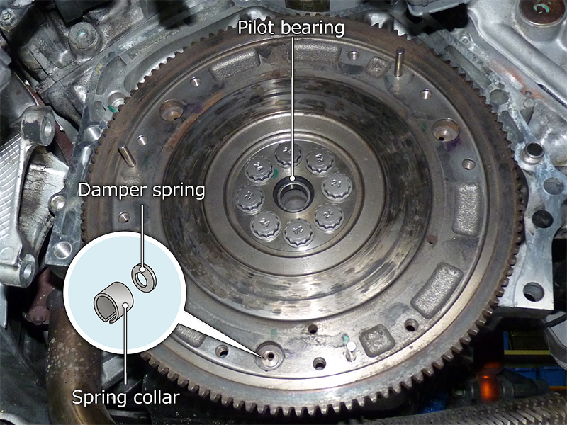
Damper springs and spring collars
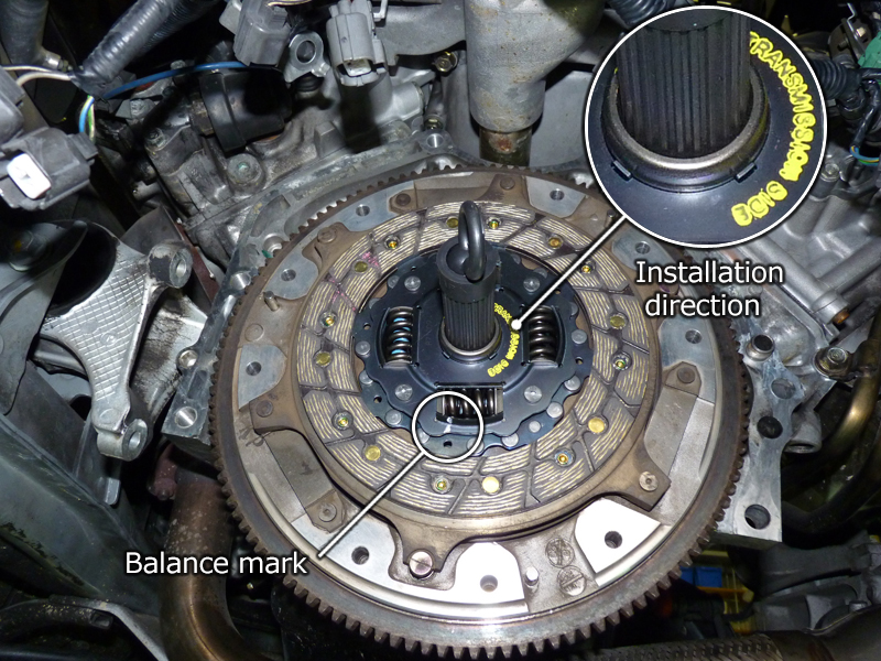
1st friction disc assembled
- The clutch disc has the installation direction marked on it. Install it as indicated. The second friction disc is marked "FLYWHEEL SIDE" and "MID SIDE", and the first friction disc is marked "TRANSMISSION SIDE" and "MID SIDE", so set them accordingly. There are also balance marks on the discs, so set them so that the markings on the second and first discs are 180° opposite. Insert a centering tool and center the clutch disc. Since it is a twin plate, the spline positions of the two discs must be aligned.
- The midplate and friction disc each have a triangular alignment mark, so align the marks when installing.

Flywheel and midplate alignment marks
- Set the clutch cover with the release bearing attached, and install the nine fixing bolts. Like the flywheel and midplate, the clutch cover also has triangular alignment marks, so set it so that it aligns with the mark on the midplate. The clutch cover fixing bolts are 12-point, so you will need a 10mm 12-point socket. To prevent deflection of the diaphragm spring, tighten the bolts diagonally as instructed in the service manual. build Clutch cover fixing bolt torque: 2.2 kg-m
- Clutch installation complete. This time, only the pilot bearing, flywheel bolt, release bearing, and friction disc were new, and the rest were used second-hand parts.
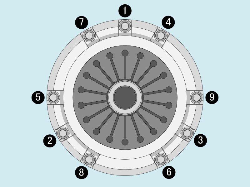
Clutch cover fixing bolt tightening sequence
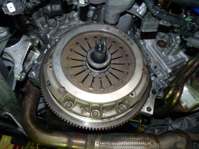
Clutch installation complete
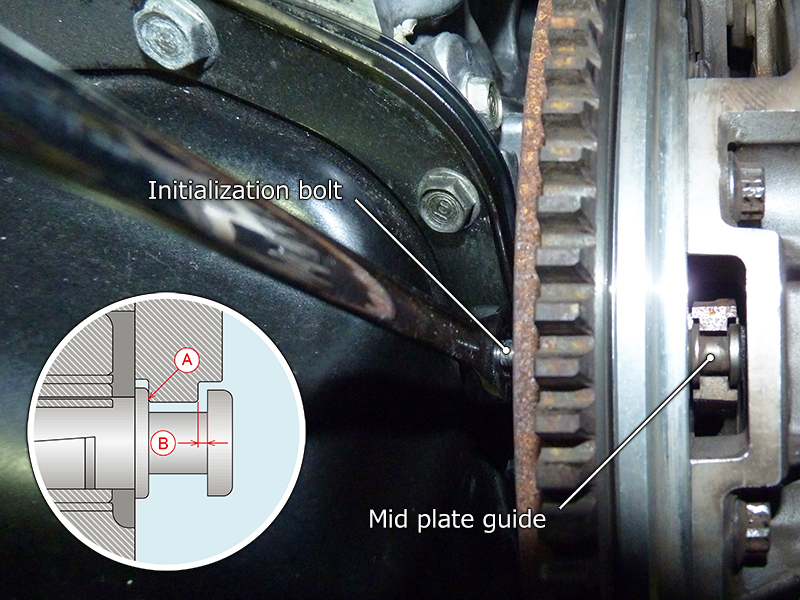
Initialize the midplate
- The mid-plate has a mechanism that maintains a constant clearance in line with disc wear. Since the clearance changes when the clutch disc is replaced with a new one, initialize the mid-plate guide to reset the clearance. Forgetting to do this will prevent the clutch from disengaging. Install M5 bolts into the three tapped holes on the back of the flywheel and tighten them so that they push the guide outward and make it slide. Tighten the bolts until the base of the guide (A) is in close contact with the mid-plate, completing the initialization. The service manual instructs you to further tighten the bolts 150 to 210 degrees from this tight fit. The 91 Coupe service manual specifies a clearance of 0.40 to 0.55 mm for (B), and 0.25 to 0.40 mm for the 92R. Before installing the transmission, apply urea grease to the release bearing and release fork.
- The most difficult part of the process in a home garage without a transmission jack is positioning the transmission.
Since we want to tilt the engine as much as possible while lowering the transmission, we remove the front beam to which the front engine mount is attached.
After supporting the oil pan with a jack, we unbolt the front engine mount and remove the front beam, then gradually lower the jack to tilt the engine.
Just like when removing the automatic transmission, we hang the manual transmission from the engine hanger, lift it from below with a garage jack, and once we've reached the desired position, we can mate it manually.
Unlike an automatic transmission, a manual transmission cannot be lifted vertically because it has a clutch on the engine side and a main shaft on the transmission side. Unlike an FR transmission, it also has a differential, making it extremely heavy, requiring considerable strength for one person to do the job (we tried doing it alone, but eventually ran out of strength and ended up having to do it with two people).
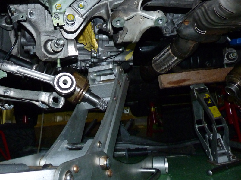
Lift the transmission with a garage jack

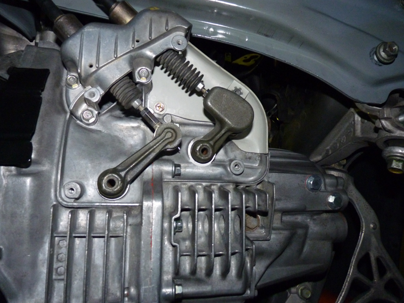
Release cylinder installation complete
- Once the transmission has been mated, we attach the engine and transmission fixing bolts, mounts, starter motor, etc. After returning the release fork to its correct position, we install the release cylinder and dust boots, etc.
- The select cable and shift cable are pulled into the interior and connected to the shift lever, and the transmission side is attached to the select lever.
- The standard adjustment values for the connection between the select cable and the shift cable on the transmission side are listed. I just installed a used cable without adjusting it, and I didn't feel any discomfort, so I didn't make any adjustments.
Select and shift cable installation complete
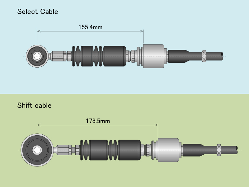
Select and shift cable adjustment values
Manual transmission installed
- Once work on the transmission is complete, install the drive shaft and assemble the suspension in the reverse order of removal.
Finally, bleed the clutch line and add transmission oil, completing work on the transmission.
At this point, the ECU has not yet been repaired, but we can confirm that power is transmitted properly and that the gearshift functions properly.
With the vehicle still jacked up, we press the clutch to start the engine, put it in first gear, and then cautiously engage the clutch while the engine is idling, and are relieved to see that the rear tires rotate properly.
Next, we shift up to fifth gear at low RPM to confirm that power is transmitted properly. Finally, we check the reverse operation to confirm that the manual transmission is functioning properly.